
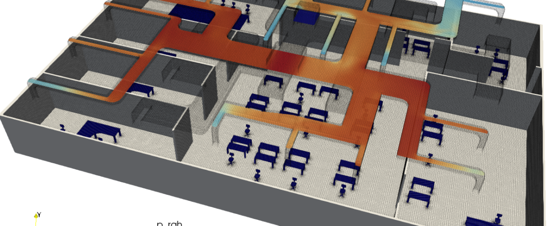
In commercial building design, an office HVAC ducting network is the vital respiratory system responsible for indoor air quality and thermal comfort. By routing conditioned air from an Air Handling Unit (AHU) through a sprawling maze of trunk lines, branch ducts, and terminal diffusers, the system aims to distribute precise heating or cooling loads to every zone in the building.
Operating a commercial ducting network efficiently requires maintaining an exact static pressure balance while strictly managing aerodynamic acoustics and fan power consumption. Because commercial offices feature fluctuating occupancy loads and complex layouts, mechanical engineers rely heavily on Computational Fluid Dynamics (CFD) to optimize air distribution, evaluate duct take-off angles, and prevent stagnant dead zones.
However, simulating an office ducting network is a deceptive fluid mechanics task. While low-pressure air feels simple, a ducting layout is packed with sharp turns, abrupt dampers, and intersecting junctions that trigger severe flow separations. If your simulation framework relies on simplified volume-flow splits or flattens these geometric transitions into a steady-state approximation, your solver will completely miss localized pressure drops—leaving your design team blind to efficiency-killing airflow maldistribution.
1. The Physics Anchor: Adverse Pressure Gradients and the Static Regain Phenomenon
The fluid dynamics inside an office HVAC duct are governed by the conservation of mass and momentum (Navier-Stokes equations) tightly coupled with the static regain principle. As air moves through a stepped network of changing cross-sections, kinetic energy and static pressure constantly trade places.
To capture this mathematically, simulations must resolve the turbulent shear layers that form when high-velocity air encounters geometric transitions:
[Air Exits AHU Fan] ➔ [Enters Main Trunk Line at High Velocity] ➔ [Duct Cross-Section Expands or Steps Down] ➔ [Velocity Drops / Static Pressure Recoups] ➔ [Localized Flow Separation & Starved Branch Lines]
- The Static Regain Barrier: When a main duct line expands or passes a major branch take-off, the air’s velocity drops. According to Bernoulli’s principle, this reduction in velocity converts dynamic pressure into static pressure (static regain).
- The Branch Separation Trap: If a branch duct splits off at an aggressive, unrounded angle, the high-velocity air cannot make the sharp turn cleanly. The airflow detaches violently from the inside wall of the take-off, creating a massive recirculation wake. This swirling eddy introduces a severe localized pressure drop, heavily starving that specific branch line of its required cubic feet per minute (CFM) while over-pressurizing downstream zones.
2. Industry Context: Where Airflow Balance Secures Occupant Productivity
Optimizing ducting pathways and achieving perfect flow balance through high-fidelity CFD directly dictates the energy footprint, green building certification, and operational margins of modern corporate real estate:
- ASHRAE 55 Thermal Comfort Compliance: Office environments require strict velocity limits (typically under 0.25 meters per second in the occupied zone) to prevent uncomfortable drafts while maintaining uniform temperatures. Engineers use CFD to design terminal diffusers, ensuring the exiting air attaches to the ceiling via the Coanda effect to mix thoroughly before dropping into workspaces.
- Acoustic Noise Suppression (NC Ratings): High-velocity air squeezing past a partially closed volume control damper (VCD) or a sharp duct elbow generates severe aeroacoustic noise. High-fidelity simulation allows teams to identify localized high-velocity spikes, resizing duct geometries to suppress the low-frequency rumbles that disrupt workplace focus.
- Variable Air Volume (VAV) System Stability: Modern offices utilize VAV boxes to modulate airflow based on real-time thermostat demands. CFD allows controls engineers to map how pressure waves from a closing VAV box propagate backward through the ducting network, preventing upstream branch lines from experiencing unexpected airflow surges.
3. The Traps & Friction: Why Office Ducting CFD Fails
Predicting the exact airflow split and pressure drop across a complex commercial building layout requires avoiding common numerical shortcuts. Defaulting to standard industrial setups leads to three severe traps:
Relying on the Idealized Equal Friction Method Blindly
Most standard HVAC duct routing projects default to sizing networks using analytical blueprints like the Equal Friction Method. While these formulas are excellent baseline tools for straight galvanized sheets, they are entirely blind to dynamic multi-component interference. If a duct layout places an elbow directly upstream of a branch take-off, the incoming velocity profile is heavily skewed. This asymmetric loading spikes the real-world pressure loss far past anything predicted by standard static loss coefficient (ASHRAE Fitting) tables.
Misconfiguring the Boundary Layer Grid near Diffuser Vanes
The ultimate test of a ducting simulation is how the air leaves the terminal diffusers to enter the room. Diffuser grilles contain intricate, angled vanes designed to throw air across wide rooms. If your volume mesh is too coarse near these thin vanes, the mathematical solver will suffer from severe numerical diffusion, artificially smoothing out the jet velocities. Without micro-scale prism layer grid refinement paired with a robust low-Reynolds turbulence model (such as the k-omega SST model), your simulation will completely miscalculate the air’s throw distance, hiding localized stagnant dead zones.
Utilizing Simplified Steady-State Solvers for Transient VAV Dampers
Because VAV box dampers continuously modulate throughout the day in response to changing solar loads and office meetings, ducting flow is inherently transient. A common pitfall is running static, steady-state CFD models under a single, static damper configuration. This approach completely flattens the transient vortex-shedding that occurs when a damper plate sits partially closed. To capture the true dynamic pressure losses and localized acoustic noise spikes, engineering teams must deploy transient Scale-Resolving Simulations (SRS).
4. Conquering the Commercial Flow Boundary
A beautiful, colorful velocity contour plot of an office ceiling layout is completely useless if your digital CFM splits do not correlate with physical building operations. Validating your office HVAC CFD pipeline requires moving past macro-scale averages and deploying fully resolved, transient fluid workflows. These digital models must be cross-referenced against empirical field metrics—such as real-time hot-wire anemometer grid data and pitot-tube duct traverses validated during physical Testing, Adjusting, and Balancing (TAB) commissioning—ensuring your static regain gradients, branch pressure losses, and diffuser throw profiles perfectly reflect physical building boundaries.
Balancing transient high-speed turbulence, non-uniform branch splits, and micro-scale diffuser vane grid tracking demands an elite technical workflow. If your engineering team is facing unexpected tenant complaints regarding hot or cold spots, dealing with unmanageable duct whistling noises, or struggling to minimize fan energy footprints to hit strict green building targets, bringing in a highly targeted technical extension can bridge the operational gap.
Author: Caesar Wiratama
Find me on Linkedin