
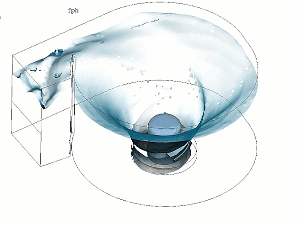
In the deployment of small-scale, decentralized renewable energy infrastructure—particularly for low-head river systems, rural micro-grids, and industrial wastewater outfalls—the gravitational water vortex turbine (GWVT) has emerged as a vital tool. Unlike traditional high-head turbines that require massive dam structures and heavy infrastructure, a vortex turbine operates on a simple, eco-friendly principle. Water enters a custom-engineered cylindrical basin tangentially, forming a powerful, stable free surface air-core vortex. The fluid’s kinetic energy concentrates into this swirl, spinning a low-head runner placed coaxially at the basin’s central exit to generate electricity.
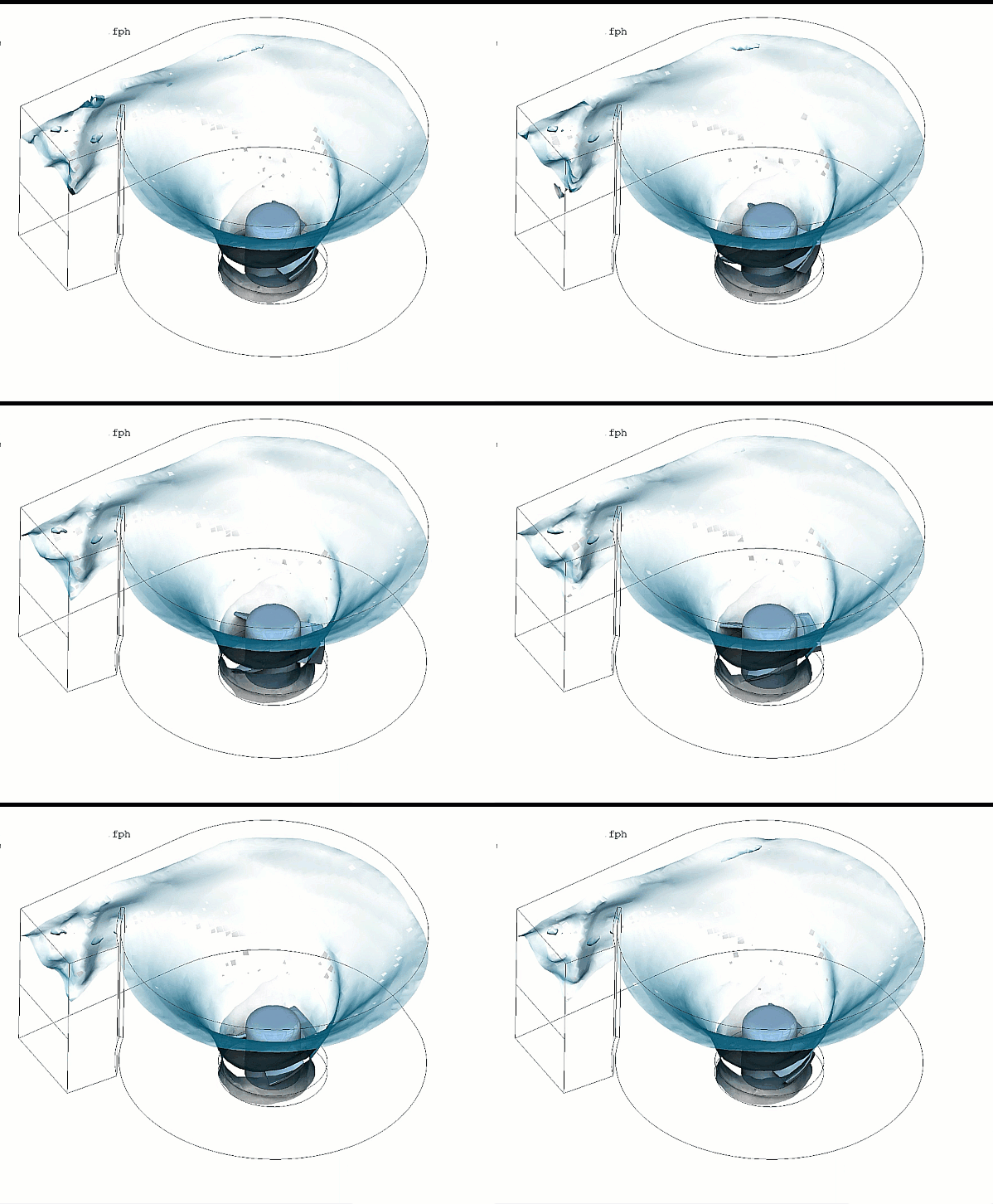
Operating a gravitational vortex turbine efficiently requires maximizing the hydrodynamic power coefficient while strictly managing the structural torque fluctuations on the runner blades and preventing core air-entrainment losses. Because water is highly dense and the formation of a stable air-core is deeply sensitive to intake geometries, engineering teams rely heavily on Computational Fluid Dynamics (CFD) to shape basin walls, optimize runner blade twist angles, and select the ideal exit orifice diameters.
However, simulating a gravitational vortex turbine is an exceptionally deceptive, highly non-linear multi-phase turbomachinery challenge. A vortex turbine does not operate in a closed, pressurized pipe loop. It relies entirely on the formation of a sharp, rotating free-surface boundary layer between water and air. If your simulation setup flattens these rapid transient interactions into a steady-state formulation or utilizes simplified rotational force approximations, your solver will suffer from vortex core dissipation—leaving your design team blind to efficiency-killing fluid short-circuits.
1. The Physics Anchor: Free-Surface VOF Tracking and Angular Momentum Acceleration
The fluid dynamics inside a gravitational vortex basin are governed by the multi-phase Navier-Stokes equations tightly coupled with a Volume of Fluid (VOF) free-surface tracking method and a Rigid Body Rotational Framework. The primary metric dictating vortex strength is the conservation of angular momentum as fluid moves radially inward toward the central exit drain.
As the incoming water stream transitions from linear intake flow to a highly accelerated rotational matrix, it maps a volatile multi-physics sequence:
[Tangential Water Intake] ➔ [Radial Acceleration Toward Exit Orifice] ➔ [Angular Velocity Spikes via Angular Momentum Conservation] ➔ [VOF Model Resolves Sharp Pressure Drop Core] ➔ [Air-Core Conically Forms Down to Runner Blades]
- The Free Vortex Acceleration: As water enters tangentially and spirals inward toward the central drain, its radius decreases. To conserve angular momentum, the fluid’s tangential velocity increases exponentially. This rapid velocity acceleration generates a massive centrifugal force field that pushes water outward against the basin walls.
- The Sharp Pressure Drop Core: According to Bernoulli’s principle, this extreme velocity spike triggers a profound static pressure drop at the central axis of rotation. When the local static pressure matches the atmospheric pressure, the air-water interface is drawn downward, conically carving out a stable free surface air-core vortex that punches completely through the center of the discharge orifice.
- The Energy Extraction Handshake: When the runner blade enters this swirling air-core boundary, it must extract energy from the high-velocity fluid sheets without disrupting the underlying vortex structure. If the runner blade geometry is poorly optimized, it will act as a physical blockage, destroying the angular velocity and causing the air-core to collapse back into a turbulent, unorganized stagnant pool.
2. Industry Context: Where Vortex Stability Secures Micro-Grid Uptime
Optimizing basin geometries, intake channel ramps, and runner blade topologies through high-fidelity multi-phase CFD directly dictates the commercial survival, fish-friendly certification, and operational lifecycles of low-head hydro assets:
- Eco-Friendly and Fish-Passage Micro-Hydro: Traditional hydro turbines utilize high-velocity shear blades that destroy local aquatic life. Gravitational vortex turbines are inherently fish-friendly because the low-pressure air-core allows fish to pass safely through the center of the basin and exit downstream completely unharmed. Engineers use CFD to map internal pressure gradients, ensuring velocity fields remain below stress thresholds required for global environmental certification.
- Decentralized Irrigation Canal Power: Agricultural irrigation channels feature low-head, continuous water drops that are ideal for GWVT systems. Operators deploy multi-phase CFD to optimize the tangential inlet notch, ensuring that changing water levels in the main canal do not drop the basin’s velocity below the critical threshold required to maintain a stable, power-generating swirl.
- Industrial Wastewater Outfall Harvesting: Large-scale chemical or cooling water processing plants dump massive volumes of water back into water bodies. Designers deploy transient vortex simulations to custom-tailor compact, conical basins that capture this waste kinetic energy before final discharge, boosting the processing facility’s net electrical efficiency.
3. The Traps & Friction: Why Vortex Turbine CFD Fails
Predicting the exact power extraction and free-surface boundary layer profiles inside a complex vortex basin requires navigating strict numerical and modeling traps:
Relying Blindly on the Moving Reference Frame (MRF) Shortcut
To bypass the computational cost of resolving a moving mesh, engineers frequently attempt to simulate the rotating runner zone using the steady-state Moving Reference Frame (MRF) or Frozen Rotor approach. While MRF is highly accurate for standard enclosed propellers spinning in a uniform stream, it is completely useless for a gravitational vortex turbine. Because the position of the air-core boundary layer shifts dynamically in response to the blade’s rotation, the flow field is inherently transient. An MRF shortcut completely flattens these time-dependent fluid interactions, failing to predict the localized vortex distortions caused by the blade tips, outputting wildly over-optimistic power generation charts.
Misconfiguring VOF Grid Resolution in the Rotating Air-Core Zone
The ultimate accuracy of a GWVT model is determined by how well the grid resolves the sharp boundary interface where the air-core meets the swirling water sheets. If your volume mesh is too coarse near the central rotational axis, or if your time steps are too large, the mathematical solver will suffer from severe numerical diffusion. This error causes the air-water interface to artificially blur and mix, bleeding energy out of the core—a phenomenon known as numerical vortex damping. Without precise, flow-aligned cylindrical mesh refinement zones tracking the air-core down to the orifice, your solver will predict that the vortex collapses under load when the physical machine is performing perfectly.
Utilizing Standard High-Reynolds Turbulence Models Uncalibrated
The fluid flow inside a free vortex is dominated by highly curved streamlines and intense rotation. Defaulting to standard, isotropic two-equation turbulence models—such as the standard k-epsilon or standard k-omega models—leads to a severe physical blindspot. These standard models are hardcoded to assume isotropic turbulence, meaning they severely over-predict turbulent viscosity in swirling regions. This numerical error artificially dampens the tangential velocity peak, predicting a weak, sluggish vortex. Overcoming this requires explicitly configuring the solver with curvature correction parameters or deploying advanced Reynolds Stress Models (RSM) that can handle highly anisotropic rotation.
4. Conquering the Multi-Phase Rotational Interface
A beautiful color velocity animation of a spinning water vortex is completely useless if your digital torque metrics and basin discharge rates do not correlate with physical field data. Validating your gravitational vortex turbine CFD pipeline requires moving past steady-state shortcuts and deploying fully resolved, transient sliding-mesh multi-phase workflows, such as Detached Eddy Simulation (DES) or Unsteady RANS paired with RSM closures.
Your simulation parameters must be cross-referenced against empirical laboratory metrics—such as ultrasonic water-level sensors mapping the exact air-core profile, torque transducer logs on the runner shaft, and Particle Image Velocimetry (PIV) maps validated on physical scale models inside circulating fluid channels—ensuring your moving mesh handshakes, VOF surface tension variables, and anisotropic turbulence parameters perfectly reflect physical hydrokinetic realities.
Author: Caesar Wiratama
Find me on Linkedin