
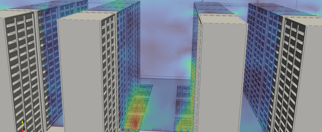
Data center cooling networks are critical operational infrastructure assets responsible for maintaining the thermal stability of high-density server racks. As cloud computing, artificial intelligence, and enterprise data processing demands accelerate, server chips dissipate exponentially higher heat fluxes within increasingly compact chassis footprints. If this thermal load is not continuously and uniformly removed, server nodes will experience localized overheating, triggering automatic thermal throttling or catastrophic hardware failure. Computational Fluid Dynamics (CFD) provides data center architects and thermal engineers with an indispensable virtual laboratory to visualize complex airflow patterns, eliminate hot spots, and evaluate energy-saving containment strategies with high precision.
Technical and Theoretical Description
From a fluid mechanics perspective, data center climate control operates on heavily coupled, forced-plus-natural (mixed) internal convection and multi-mode heat transfer governed by the three-dimensional, compressible Navier-Stokes equations and the energy equation. Air circulation is driven by Computer Room Air Conditioning (CRAC) or Computer Room Air Handler (CRAH) units that push chilled air into a raised floor plenum or open room, which is then drawn through server chassis by high-velocity internal cooling fans before exhausting into return paths. Because this environment features a mixture of high-velocity supply jets and chaotic, buoyancy-driven thermal plumes rising off hot servers, CFD simulations utilize advanced turbulence models. The Reynolds-Averaged Navier-Stokes (RANS) Shear Stress Transport (k-omega SST) or Realizable k-epsilon formulations are widely used due to their stability in tracking boundary layer separation along complex rack surfaces.
The primary theoretical focus in data center modeling centers on evaluating airflow distribution uniformity and thermal management metrics via a conjugate heat transfer (CHT) framework. Heat transfer through solid server casings and heat sinks is governed by Fourier’s Law, while convection into the air stream is calculated using Newton’s Law of Cooling. Rather than explicitly meshing millions of micro-scale processor fins—which is computationally prohibitive—engineers represent the internal server architecture as anisotropic porous media zones with customized directional flow resistance coefficients. The core performance metrics evaluated include the Supply Index (SI), Return Index (RI), and specialized thermal indices defined by plain-text empirical mathematical formulas:
- SHI (Sensible Heat Index): Evaluates the ratio of total heat infiltration into the cold aisles.
- RHI (Return Heat Index): Quantifies the efficiency of the hot air return path back to the CRAC units.
- Capture Index (CI): Measures the fraction of air emitted by a rack that is successfully trapped by the local containment system, ensuring that hot exhaust does not recirculate into the cold supply stream.
Business Value of CFD Implementation
From a commercial viewpoint, deploying CFD in data center design and operational planning yields massive capital expenditure (CapEx) savings and heavily drives down ongoing operational expenditures (OpEx). Building a physical data center facility involves multimillion-dollar investments in chiller plants, backup generators, and air handling networks. CFD acts as a risk-free virtual proving ground during the facility planning phase, enabling design teams to test dozens of tile perforation layouts, containment configurations, and rack power distributions in software. This ensures the target cooling capacity is achieved before purchasing equipment, preventing the over-specification and procurement of oversized, underutilized cooling assets.
In terms of OpEx, a CFD-refined thermal layout directly slashes data center electricity bills and maximizes hardware reliability. Cooling systems typically account for up to 40% of a data center’s total energy consumption, a major component of the facility’s Power Usage Effectiveness (PUE) metric. CFD optimization allows facility managers to safely raise CRAC supply air temperatures while ensuring that no individual server exceeds its thermal threshold. Every degree Celsius increase in supply air temperature yields substantial annual utility savings by reducing chiller workloads and maximizing the runtime of economizers (free cooling). Furthermore, eliminating hot spots prevents premature component degradation, dramatically reducing forced hardware replacements and safeguarding enterprise clients against costly, brand-damaging server downtime.
Challenges of CFD in Data Center Modeling
Despite its analytical power, simulating an active data center server room introduces steep multi-scale physical and numerical challenges. The foremost obstacle is the extreme geometric scale discrepancy combined with massive flow obstructions. A single enterprise data center hall can span thousands of square meters and house hundreds of high-density racks, yet the simulation must simultaneously capture millimeter-scale raised floor tile perforations, server chassis vents, and clearance gaps around cable trays. Fully meshing these intricate features explicitly across a macro-scale domain generates an unmanageable cell count that strains typical high-performance computing resources.
Another major hurdle is characterizing the transient, highly dynamic nature of operational workloads. Server power draw is rarely static; it fluctuates rapidly based on computational demands, causing server fan speeds and heat dissipation rates to spike unpredictably. If a simulation simplifies these boundaries into static averages, it misses transient thermal lagging and localized heat pooling that occur during peak computational bursts. Furthermore, modeling buoyancy-driven flows under mixed convection conditions requires a highly stable pressure-velocity coupling mechanism; any minor numerical imbalance in the density-temperature source term can cause artificial numerical oscillations, ruining the validity of the thermal containment predictions.
Solutions for High-Fidelity Simulation
To overcome these multi-scale and transient challenges, modern data center engineering workflows utilize specialized numerical sub-models and highly structured meshing strategies. Engineers resolve the extreme geometric scale discrepancies by representing perforated floor tiles and server rack profiles as localized porous jump or anisotropic porous media zones, where directional viscous and inertial resistance coefficients are calibrated via empirical face-velocity and pressure-drop curves. The computational domain is built using high-quality hexahedral or polyhedral grids, with heavy grid refinement concentrated around cold/hot aisle containment boundaries, server intake/exhaust faces, and near CRAC return plenums where steep velocity and thermal gradients exist.
To handle dynamic computational workloads without overwhelming processing budgets, steady-state CHT simulations are used to establish baseline configurations, followed by targeted transient simulations that program server heat loads using time-dependent profile tables or customized user-defined functions (UDFs). Real-world cooling unit failures—such as a sudden blackout of a critical CRAC unit—are simulated transiently to evaluate the thermal ride-through time of the room before hardware damage occurs. Finally, to eliminate identified thermal bypass or hot air recirculation, engineers use the CFD environment to virtually iterate design corrections, such as installing blanking panels in empty rack slots, adjusting the open area of perforated tiles, or implementing full Hot/Cold Aisle Containment (HAC/CAC) systems. Validating these modifications digitally guarantees a highly responsive, low-PUE, and perfectly reliable data center layout before physical hardware deployment.
Author: Caesar Wiratama
Find me on Linkedin