
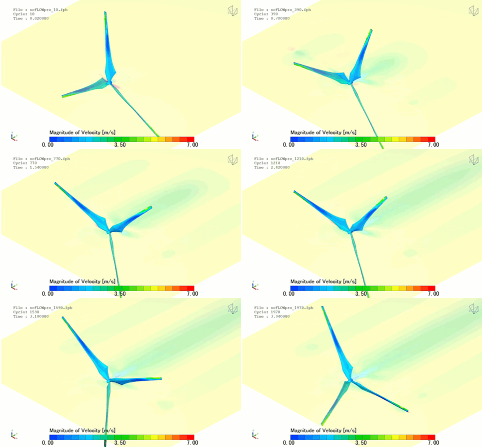
In the global transition toward zero-carbon energy grids, the horizontal axis wind turbine (HAWT) stands as the premier technology for high-capacity power generation. Operating with a rotor plane oriented perpendicular to the wind, modern utility-scale HAWTs feature immense composite blades that stretch past 100 meters in length. As the wind hits these rotating aerodynamic profiles, it generates a lift differential that drives the main rotor shaft, converting kinetic atmospheric energy into mega-watt-scale electrical power.
Operating a utility-scale wind turbine efficiently requires maximizing the aerodynamic power coefficient (Cp) while strictly managing structural aeroelastic fatigue and blade acoustic profiles. Because a single turbine blade costs hundreds of thousands of dollars to manufacture, engineering teams rely heavily on Computational Fluid Dynamics (CFD) to shape airfoil cross-sections, map wake recovery profiles, and minimize tip-clearance losses.
However, simulating a horizontal axis wind turbine is a highly deceptive, transient multi-body aerodynamic challenge. A modern turbine does not spin in a perfect vacuum or a smooth, uniform stream; it cuts through a highly sheared, volatile Atmospheric Boundary Layer (ABL). If your simulation framework relies on simplified steady-state approximations or flattens the blade-tip regions into coarse grids, your solver will suffer from numerical vortex damping—leaving your design team blind to efficiency-killing flow separations and false torque peaks.
1. The Physics Anchor: Rotational Augmentation and Tip-Vortex Shearing
The fluid dynamics surrounding a high-speed HAWT rotor are governed by the compressible Navier-Stokes equations tightly coupled with an active Moving Mesh Rotational Framework. The fluid path transitions through highly complex, three-dimensional aerodynamic zones:
[Wind Hits Rotating Blade] ➔ [Coriolis & Centrifugal Forces Augment Boundary Layer] ➔ [Delay of Dynamic Stall Peak] ➔ [High-Pressure Fluid Leaks Across Blade Tip] ➔ [Rolls Up Violent, Helical Tip Vortex]
- The Rotational Augmentation Phenomenon: Unlike a static aircraft wing, a rotating wind turbine blade generates immense centrifugal and Coriolis forces. These forces act as a fluid vacuum, pumping the slow-moving boundary layer air radially outward toward the blade tip. This unique mechanism actively stabilizes the flow, delaying the onset of aerodynamic stall at the blade root, allowing the turbine to extract significantly more torque at low tip speed ratios than predicted by static wing theory.
- The Tip-Vortex Discontinuity: At the outermost edge of the blade, high-pressure air from the pressure side violently leaks over the tip to the low-pressure suction side. This cross-flow interaction coils the fluid into a highly concentrated, spinning helical tip vortex. The core of this vortex experiences a severe static pressure drop, creating an immediate drag penalty that opposes rotor movement.
- The Atmospheric Velocity Shear: The incoming wind velocity increases non-linearly with height following a logarithmic profile. This means as a single blade rotates from its lowest vertical position to its highest vertical peak, it experiences continuous, cyclical shifts in relative velocity and angle of attack, forcing the entire blade structure into a transient aerodynamic loading matrix.
2. Industry Context: Where Wake Management Secures Megawatt Outputs
Optimizing aerodynamic blade contours, twist distributions, and multi-turbine array layouts through high-fidelity CFD directly dictates the financial payback and structural survival of wind energy assets:
- Multi-Gigawatt Offshore Wind Farms: In massive offshore arrays, downstream turbines sit directly inside the turbulent, energy-starved wake generated by upstream turbines. Engineers use large-scale wake-interaction CFD to determine optimal turbine-to-turbine spacing. Precise wake mapping prevents downstream rotors from suffering a 15% to 20% power deficit while protecting them from violent wake-induced structural vibrations.
- Aeroacoustic Noise Reduction and Public Certification: HAWT systems are heavily deployed near coastal communities and rural regions, making strict noise compliance a critical design constraint. When the high-velocity tip vortex interacts with the trailing edge of the blade, it radiates high-frequency broadband noise (aerodynamic swish). Engineers use transient CFD to design custom trailing-edge serrations (owl-wing shapes) to break up the vortex core and lower noise emissions by several decibels.
- Aeroelastic Fluid-Structure Interaction (FSI): Modern turbine blades are so long and flexible that they bend and twist significantly under intense wind gusts. Designers deploy fully coupled, 2-way FSI simulations to map how this structural deformation alters the aerodynamic angle of attack in real-time, preventing dangerous blade flutter that can cause the blade to physically strike the structural support tower.
3. The Traps & Friction: Why Horizontal Axis Turbine CFD Fails
Predicting the exact power curves, structural fatigue loads, and acoustic profiles of massive rotating blades requires avoiding common computational shortcuts. Defaulting to standard configurations leads to three severe traps:
Relying Blindly on the Moving Reference Frame (MRF) Shortcut
To dodge the computational cost of a physically moving grid, engineers frequently simulate wind rotors using the steady-state Moving Reference Frame (MRF) or Virtual Rotor (Actuator Disk) approach. While this shortcut can give a rough estimate of calm-water power generation at peak efficiency, it is entirely blind to atmospheric shear layer fluctuations. Because a real HAWT cuts through a velocity-sheared wind field, its flow is inherently transient. An MRF shortcut completely flattens these cyclical variations, failing to predict the cyclic growth and collapse of root stalls and wake breakdowns, outputting highly inaccurate annual energy production (AEP) metrics.
Misconfiguring the Grid Resolution in the Tip-Vortex Path
A tip vortex is exceptionally sensitive to numerical damping. If your volume mesh cells grow larger or become highly skewed as they stretch downstream of the blade tip, the mathematical solver will introduce massive numerical diffusion. This error causes the computed helical vortex core to artificially smear, dissipate, and lose its low-pressure peak within a few meters of the rotor plane. Without micro-scale cylindrical mesh refinement zones explicitly tracking the helical vortex path downstream, your solver will output a false low-drag dataset because it cannot see the wave energy escaping, leading to a severe over-prediction of wind farm efficiency.
Utilizing Standard Isotropic Turbulence Models Uncalibrated
The fluid flow inside a trailing wind wake is dominated by highly curved streamlines and intense rotation. Defaulting to standard, isotropic two-equation turbulence models—such as the standard k-epsilon or standard k-omega SST models—leads to a severe physical blindspot. These models assume uniform turbulence in all directions, meaning they severely over-predict turbulent viscosity in spinning regions. This numerical error artificially dampens the wake velocity deficit, predicting that the wind speeds recover much faster behind a turbine than they can in physical reality, causing developers to space real-world turbines too closely together.
4. Conquering the Atmospheric Aerodynamic Interface
A beautiful, colorful velocity contour plot of a streamlined wind turbine profile is completely useless if your digital power coefficients (Cp) and thrust forces do not correlate with physical field testing. Validating your HAWT CFD pipeline requires moving past static shortcuts and deploying fully coupled, transient sliding-mesh or overset grid scale-resolving workflows, such as Detached Eddy Simulation (DES) or Large Eddy Simulation (LES).
Your simulation parameters must be cross-referenced against empirical laboratory and field metrics—such as multi-component force balance telemetry inside specialized atmospheric wind tunnels and full-scale LIDAR wake tracking data validated on real operational turbines according to international standard IEC 61400—ensuring your moving mesh interfaces, boundary layer transitions, and trailing vortex profiles perfectly reflect physical aerodynamic realities.
Author: Caesar Wiratama
Find me on Linkedin