
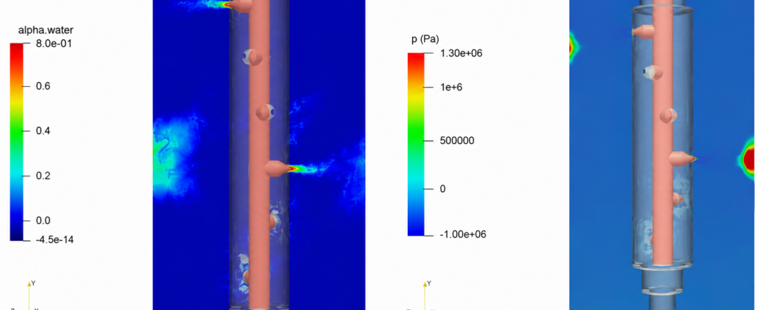
In upstream oil and gas production, the jet perforator assembly (or perforation gun) is the definitive tool used to establish a flow path between the wellbore and the hydrocarbon reservoir. By detonating a series of shaped explosive charges, the perforator generates a high-velocity, hyper-plastic jet of molten metal that punches cleanly through steel well casings, cement sheaths, and deep into the surrounding rock matrix to form productive flow channels.
Operating a perforation run efficiently requires maximizing the total depth of penetration and ensuring an optimal hole diameter while strictly managing the dynamic pressure shockwaves within the wellbore. Because unmanaged detonation shockwaves can buckle the production tubing or destroy downhole isolation packers, completion engineering teams rely heavily on Computational Fluid Dynamics (CFD)
to analyze transient pressure spikes, evaluate gun carrier venting, and map downhole fluid movement.
However, simulating an oil and gas jet perforator is an exceptionally deceptive, highly multi-scale multiphase task. The detonation occurs within microseconds, forcing gas expansions that transition from hypersonic shock fronts to highly compressible transient waves. If your simulation setup relies on simplified, idealized pressure surge formulas or flattens the explosive boundaries into coarse, static grids, your solver will completely miss localized dynamic underbalance anomalies—leaving your completion team blind to smeared casing plumes and hidden formation fractures.
1. The Physics Anchor: Detonation Wave Discontinuities and Conjugate Shock Handshakes
The transient fluid dynamics of a jet perforator are governed by highly compressible Navier-Stokes and energy equations coupled with a chemical Equation of State (EOS)—such as the Jones-Wilkins-Lee (JWL) formulation—to track explosive gas expansion. The downhole environment breaks into highly distinct physical regimes:
[Shaped Charge Detonates] ➔ [Hypersonic Gas Expansion via JWL Model] ➔ [Extreme Pressure Wave Strikes Gun Wall] ➔ [Conjugate Shockwave Handshake into Wellbore Fluid] ➔ [Dynamic Underbalance / Well Flow Inception]
- The Detonation Front Discontinuity: When the shaped charge fires, the high explosive converts into gaseous products at extreme speeds, generating pressures scaling past hundreds of thousands of atmospheres. The solver tracks this sharp, moving boundary layer using explicit, density-based compressible formulations.
- The Wellbore Fluid Shock Handshake: As the shockwave blasts through the perforation gun wall, it undergoes a complex energy transfer (conjugate shock handshake) into the surrounding wellbore fluid. The liquid compresses instantly, throwing a high-intensity pressure pulse up and down the wellbore casing string.
- Dynamic Underbalance Topologies: Directly behind the primary shockwave, the rapid expansion of gas creates a localized, short-lived drop in pressure below the reservoir’s natural pressure. This dynamic underbalance acts as a fluid vacuum, instantly pulling crushed rock and debris out of the newly formed tunnel to clean the perforation hole before it can plug.
2. Industry Context: Where Shockwave Management Safeguards Downhole Assets
Optimizing perforation gun geometries and predicting transient pressure surges through high-fidelity multi-physics simulation directly dictates the reservoir productivity, completion longevity, and tool survivability of high-pressure wells:
- High-Tier Deepwater Completion Operations: Deepwater wells operate under immense hydrostatic pressures. Engineers use transient CFD to optimize the spatial distribution and timing of the explosive charges, ensuring the overlapping pressure waves do not constructively interfere to split the structural outer casing of the wellbore.
- Perforation Tunnel Cleanup and Skin Factor Reduction: If a perforation tunnel remains packed with crushed rock and cement debris, the well suffers from a high skin factor (fluid flow restriction). Designers deploy transient underbalance simulations to fine-tune gun venting apertures, maximizing the sudden, localized suction force required to clean out the tunnel matrix.
- Tubing Conveyed Perforating (TCP) Safe Structural Anchoring: TCP strings can span hundreds of meters inside a horizontal wellbore. Engineers use coupled fluid-structure interaction (FSI) to map how the microsecond shockwaves deform the internal tool string, calculating anchor and packer placement to prevent the mechanical string from tearing away from its downhole anchors.
3. The Traps & Friction: Why Jet Perforator CFD Fails
Predicting the exact peak pressure surge and transient fluid drawdown inside a deep-well casing requires avoiding common numerical shortcuts. Defaulting to standard configurations leads to three severe traps:
Relying Solely on Idealized 1D Analytical Pressure Surge Software
The most common and dangerous pitfall in perforation engineering is relying exclusively on traditional, 1D analytical pressure surge codes. These legacy tools evaluate shockwaves as uniform, flat planes traveling down a smooth pipe, completely ignoring three-dimensional fluid reflections, gun carrier asymmetries, and casing eccentricities. In reality, the shock wave reflects violently off the curved wellbore walls, creating localized, off-center force spikes. By flattening these physics, a 1D model smooths over the peak structural stresses, leaving your tool string exposed to unpredicted physical distortion.
Utilizing Pressure-Based Solvers for High Mach Shock Tracking
To minimize processing times across large wellbore sectors, engineers frequently make the mistake of running perforation simulations using a standard pressure-based coupled solver. While pressure-based solvers are brilliant for subsonic liquid loops, they struggle completely when handling the extreme, hypersonic gas expansions of an explosive detonation. Failing to deploy an explicit, density-based compressible solver means the mathematical equations cannot handle the extreme discontinuities at the shock front. The solver will introduce severe numerical damping, smoothing out the true peak pressure pulse and outputting deeply flawed structural load datasets.
Misconfiguring the Grid Resolution in the Gun Vent Ports
The ultimate test of a perforation simulation is how the expanding gas exhausts through the newly formed holes in the gun carrier into the wellbore. These vent ports form tight, high-shear throat geometries where fluid velocity spikes to supersonic speeds. If your volume mesh is too coarse around these openings, the solver will suffer from massive numerical diffusion, artificially smoothing out the local pressure gradients. Without micro-scale prism layer grid refinement paired with a robust scale-resolving turbulence model (such as Detached Eddy Simulation, or DES), your simulation will completely miscalculate the transient drawdown rate, missing early signs of dynamic underbalance failure.
4. Conquering the High-Energy Multi-Phase Interface
A stunning color animation of an explosive burst inside a digital wellbore is completely useless if your computed transient pressure log metrics do not correlate with physical downhole telemetry. Validating your jet perforator design CFD pipeline requires moving past single-phase shortcuts and deploying fully coupled, transient density-based multi-phase loops. Your simulation parameters must be cross-referenced against empirical laboratory metrics—such as high-speed pressure transducer records from pressurized surface test vessels and transient flow data from sand-packed target core flow tests—ensuring your equations of state, shock reflection variables, and structural damping coefficients perfectly reflect physical downhole boundaries.
Balancing transient hypersonic shock tracking, non-linear explosive equations of state, and micro-scale vent port grid resolutions demands an elite technical workflow. If your completion design team is facing unexpected tool string damage during field runs, dealing with under-performing well flow tracking due to poor tunnel cleanup, or struggling to minimize shock loads near sensitive downhole electronics, bringing in a highly targeted technical extension can bridge the operational gap.
Author: Caesar Wiratama
Find me on Linkedin