
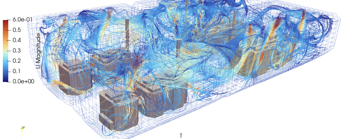
Ship engine rooms are among the most thermally demanding internal environments in mechanical engineering. Housing massive prime movers, diesel generators, exhaust manifolds, and high-voltage electrical switchgear, these enclosed spaces generate colossal amounts of radiant heat. An inadequately engineered HVAC and ventilation system can lead to severe operational issues: localized thermal traps that trigger electronic system failures, suffocating conditions for the crew, and starved combustion air for the main engines, which directly reduces fuel efficiency. Computational Fluid Dynamics (CFD) provides naval architects and marine engineers with a high-fidelity virtual engine room to map complex air distribution profiles, evaluate localized temperatures, and optimize machinery layouts with extreme precision.
Technical and Theoretical Description
From a thermal-fluid dynamics perspective, an engine room HVAC system operates on highly complex, coupled multi-mode heat transfer and forced-plus-natural (mixed) internal convection governed by the three-dimensional, compressible Navier-Stokes and energy equations. Air circulation is driven by massive supply fans that push ambient outdoor air through complex duct networks and weather heads, which then mixes with intense buoyancy-driven thermal plumes rising off uninsulated engine blocks and exhaust pipes. To capture these high-velocity supply jets alongside chaotic, buoyancy-driven thermal swirling, CFD simulations deploy advanced turbulence closures, most notably the Reynolds-Averaged Navier-Stokes (RANS) Shear Stress Transport (k-omega SST) or Realizable k-epsilon models due to their stability in tracking adverse pressure gradients and fluid-solid thermal interactions.
A primary theoretical requirement in this application is the calculation of Conjugate Heat Transfer (CHT) coupled with high-intensity thermal radiation. Heat transfer via conduction through structural steel bulkheads and machinery walls is solved using Fourier’s Law, while fluid-side convection is calculated using Newton’s Law of Cooling. Because component surface temperatures can be exceptionally high, surface-to-surface radiation is computed simultaneously using the Discrete Ordinates (DO) or Surface-to-Surface (SST) radiation model to capture the immense radiant heat flux passing through the air. The core performance metrics evaluated include the local air temperature distribution, velocity uniformity, and pressure drops across supply grilles. These metrics are processed to verify that ambient conditions remain within strict international maritime standards, ensuring that maximum temperatures near critical electrical switchboards stay below specified failure thresholds (typically 45 degrees Celsius) and that the combustion air intake zones maintain an uncompromised supply density.
Business Value of CFD Implementation
From a commercial viewpoint, deploying CFD to analyze and refine engine room ventilation yields substantial capital expenditure (CapEx) savings and directly protects multi-million dollar maritime assets. Building a physical, full-scale mock-up of a complex commercial vessel engine room is financially impossible. CFD acts as a risk-free virtual test rig during the vessel design phase, allowing engineering teams to test dozens of louvre placements, duct configurations, and fan capacities in software, compressing the engineering timeline and eliminating the catastrophic risk of post-construction structural modifications on a completed hull.
In terms of operational expenditures (OpEx), an optimized ventilation layout directly drives vessel fuel economy and minimizes forced maintenance downtime. Main engines draw their combustion air directly from the engine room space; if the HVAC layout permits thermal recirculation, the intake air becomes overheated and less dense, which degrades the engine’s volumetric efficiency and increases fuel consumption. CFD optimization ensures the delivery of cool, dense air straight to the intakes, maximizing combustion efficiency and saving thousands of dollars in fuel per voyage. Furthermore, preventing localized hot spots shields sensitive automated control systems from premature thermal degradation, drastically reducing the risk of mid-voyage electronic blackouts and forced vessel towing costs.
Challenges of CFD in Engine Room Modeling
Despite its analytical power, simulating an active ship engine room introduces steep multi-scale physical and numerical challenges. The foremost obstacle is the extreme geometric complexity coupled with a vast scale discrepancy. A standard engine room spans dozens of meters and contains a labyrinth of structural pillars, cable trays, small-bore piping, and catwalks. Attempting to mesh every minor bracket and pipe explicitly creates an unmanageable cell count that strains typical high-performance computing resources.
Another major hurdle is accurately characterizing the heat source boundaries. Manufacturers often provide only the gross radiant heat loss value for a piece of machinery rather than a detailed surface temperature distribution. If engineers oversimplify these inputs by applying uniform heat fluxes across massive geometries, the simulation will completely miss the intense localized thermal plumes that rise off unshielded exhaust components, leading to inaccurate temperature predictions. Furthermore, modeling the system under transient emergency scenarios—such as a sudden engine room fire or a total blackout where forced ventilation fans halt and the system relies entirely on transient natural buoyancy—introduces highly unstable non-linear source terms that are exceptionally prone to numerical divergence.
Solutions for High-Fidelity Simulation
To overcome these geometric complexity and multi-scale challenges, modern maritime engineering workflows utilize specialized numerical simplification techniques and tightly controlled mesh strategies. Engineers resolve the extreme geometric clutter by using simplified bounding-box geometries for secondary components while applying custom volumetric momentum-loss coefficients (porous media approximations) to represent dense pipe racks and cable trays. Primary heat sources, such as the main engine blocks and turbochargers, are discretized using high-quality unstructured polyhedral or hex-dominant meshes with dense prism layer inflation along the fluid-solid interfaces to perfectly capture the thin thermal boundary layers.
To compensate for missing manufacturer surface data, engineers use multi-zone CHT modeling, defining internal fluid and material properties for the engine blocks and insulation blankets so the software can naturally compute realistic outer surface temperatures. Real-world operational profiles, including maximum tropical ambient conditions and variable engine loads, are enforced via structured boundary profiles. Finally, to eliminate identified thermal traps or flow stagnation zones, engineers use the CFD environment to virtually iterate design counter-measures. This includes introducing steering vanes inside the main ducting, adjusting the discharge angle of supply terminals, or modifying the placement of extract fans. Validating the success of these operational changes in software guarantees a safe, energy-efficient, and regulatory-compliant engine room layout before steel cutting begins at the shipyard.
Author: Caesar Wiratama
Find me on Linkedin