
Thermal management is a critical engineering requirement in modern electronics design, spanning consumer smartphones, high-performance computing centers, and electric vehicle power modules. As semiconductor components scale down in size while dissipating exponentially higher power densities, managing heat becomes the primary bottleneck for system reliability and performance. Excessive operating temperatures accelerate component degradation, trigger thermal throttling, and can lead to catastrophic system failure. Computational Fluid Dynamics (CFD) provides thermal engineers with an indispensable virtual laboratory to simulate complex heat transfer mechanisms, analyze airflow paths, and optimize cooling solutions with high precision.
Technical and Theoretical Description
From a physics perspective, electronics thermal management involves coupled multi-mode heat transfer, combining solid-domain conduction, fluid-domain convection, and surface-to-surface radiation. The system is governed by the three-dimensional Navier-Stokes equations for fluid flow coupled with the energy equation for temperature distribution. Because cooling air moving through heat sinks, vents, and internal chassis channels is often turbulent, designers use advanced turbulence models. The Reynolds-Averaged Navier-Stokes (RANS) Shear Stress Transport (k-omega SST) model is widely utilized due to its superior accuracy in predicting boundary layer separation and flow behavior near complex solid geometries.
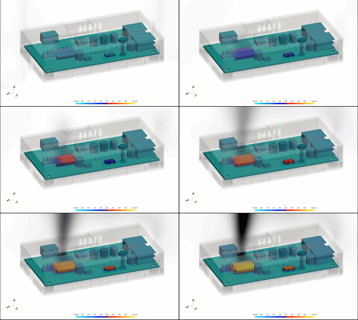
A fundamental theoretical focus in electronics cooling is Conjugate Heat Transfer (CHT), which solves the thermal interaction between solid and fluid domains simultaneously. The core theoretical metrics evaluated include junction temperature, thermal resistance, and pressure drop. Heat transfer via conduction through printed circuit boards (PCBs) and silicon dies is described by Fourier’s Law, while convection into the surrounding fluid is evaluated using Newton’s Law of Cooling. The heat transfer coefficient is calculated based on localized fluid velocity and boundary layer thickness. Additionally, for tightly enclosed systems where fluid velocities are low, natural convection driven by buoyancy forces must be captured using the Boussinesq approximation to ensure accurate buoyancy-driven flow paths are mapped.
Business Value of CFD Implementation
From a commercial standpoint, integrating CFD into the electronics development lifecycle yields massive capital expenditure (CapEx) savings and accelerates product time-to-market. Building physical prototypes of multi-layered PCBs, custom aluminum heat sinks, and vapor chambers is incredibly expensive and time-consuming. CFD acts as a rapid virtual prototyping environment, allowing thermal teams to evaluate dozens of placement configurations, component layouts, and venting designs in software before freezing the hardware architecture.
In terms of operational value and product reliability, CFD-optimized thermal design directly translates to lower operational expenditures (OpEx) and higher customer satisfaction. For data centers, optimizing airflow paths and eliminating localized hot spots reduces the energy required by facility air-conditioning systems, yielding substantial savings on electricity bills. For consumer devices like smartphones or laptops, efficient thermal management maximizes processing performance by preventing thermal throttling. By delivering hardware that runs cooler and lasts longer without throttling, electronics manufacturers can protect their brand reputation and reduce costly warranty claims.
Challenges of CFD in Electronics Thermal Modeling
Despite its analytical power, simulating electronics thermal systems introduces steep multi-scale physical and numerical challenges. The foremost obstacle is the extreme discrepancy in geometric scales. A computational domain may encompass a large server rack or an entire chassis, yet it must simultaneously resolve micron-scale thermal interface materials (TIMs), sub-millimeter copper traces on a PCB, and fine fins on a heat sink. Meshing these disparate scales accurately requires an immense cell count, demanding massive computational resources.
Another major hurdle is accurately capturing the non-linear physics of specialized cooling components. Modern electronics heavily rely on phase-change devices like heat pipes, vapor chambers, and liquid cooling cold plates to move heat away from high-power chips. Simulating the internal boiling and condensation cycles within a vapor chamber or tracking the micro-channels of a liquid cold plate introduces complex two-phase flow physics that are highly prone to numerical instability. Furthermore, characterizing anisotropic thermal conductivity across multi-layered PCBs with varying copper distributions remains a highly tedious boundary modeling challenge.
Solutions for High-Fidelity Simulation
To overcome these multi-scale and multi-phase challenges, modern thermal engineering workflows combine advanced meshing strategies with specialized physical sub-models. Engineers resolve geometric scale discrepancies by utilizing hex-dominant or polyhedral unstructured meshing paired with tight prism layer inflation along fluid-solid interfaces to accurately capture the thermal boundary layer. Components like heat pipes and multi-layer PCBs are efficiently represented using lumped parameter models or anisotropic thermal material definitions, where directional thermal conductivity is calculated mathematically based on copper-to-FR4 volume ratios rather than meshing every trace explicitly.
To handle complex phase-change devices without overwhelming computational budgets, equivalent thermal resistance networks are embedded into the solid domain of the simulation. For high-fidelity liquid cooling loops, transient simulations are deployed to track localized fluid warming and pressure drops across micro-channel configurations. Finally, to find the absolute optimal design, engineers couple the CFD solver with automated parametric optimization algorithms. This allows the software to automatically iterate through variable heat sink fin spacings, fan speeds, and vent placements to find the lowest possible junction temperature, ensuring a robust and reliable thermal blueprint before moving to mass production.
Author: Caesar Wiratama
Find me on Linkedin