
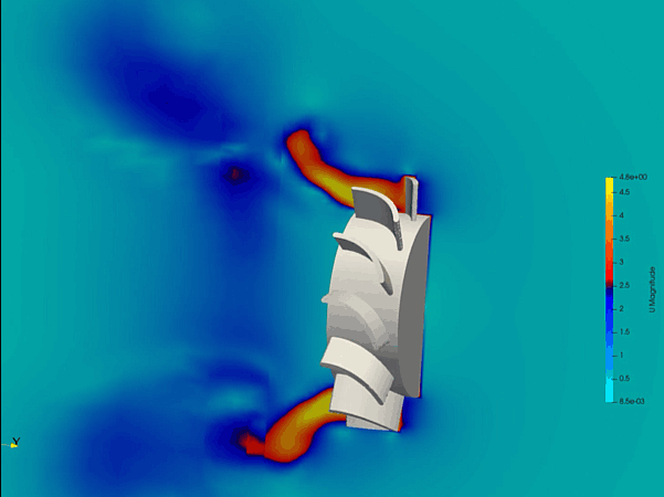
Electronic cooling fans are vital thermal management assets deployed across consumer electronics, data centers, and automotive systems to prevent component overheating. As processors and power electronics grow more compact and power-dense, the demand for high-performance, quiet, and energy-efficient cooling increases. Traditional design methods rely on trial-and-error prototyping that cannot easily capture complex, rotating fluid physics. Computational Fluid Dynamics (CFD) provides hardware engineers with a digital laboratory to visualize airflow, calculate pressure distributions, and optimize fan blade geometry with extreme precision.
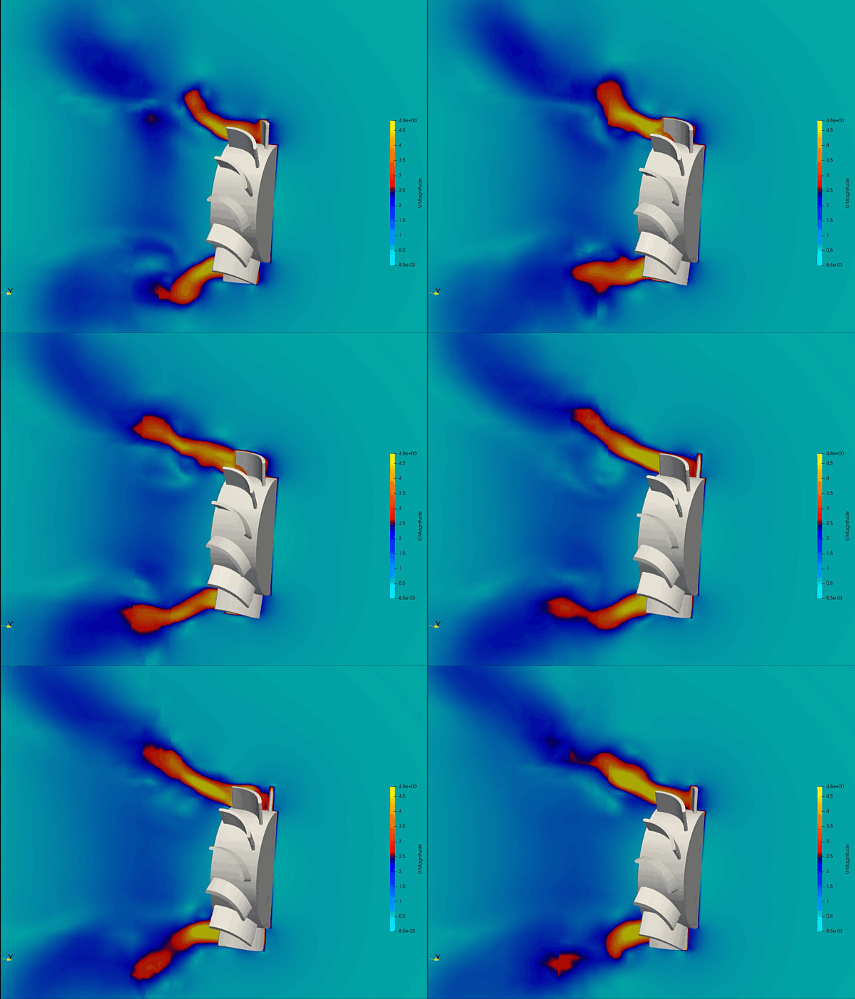
Technical and Theoretical Description
From a physics perspective, an electronic fan operates on internal turbomachinery fluid dynamics characterized by high-velocity rotational flows, boundary layer separation, and turbulent wake propagation. The flow field around the fan blades is governed by the three-dimensional Navier-Stokes equations. Because the air moving through the fan hub and blade tips exhibits intense shear and swirling turbulence, designers use advanced turbulence models. The Reynolds-Averaged Navier-Stokes (RANS) Shear Stress Transport (k-omega SST) model is universally applied due to its precision in tracking adverse pressure gradients and boundary layer separation along curved surfaces.
To model the continuous rotation of the fan blades within a stationary electronic enclosure, CFD utilizes specialized frameworks. The Multiple Reference Frame (MRF) approach is used for steady-state approximations, while the transient Sliding Mesh or Overset mesh method physically rotates the blade domain for high-fidelity time-dependent simulations. The primary theoretical metrics evaluated include the volumetric flow rate, static pressure rise, and aerodynamic shaft torque. The fan’s operating point is determined by overlaying the fan performance curve with the system resistance curve of the electronic enclosure. Furthermore, to evaluate fan noise, aeroacoustic formulations like the Ffowcs Williams-Hawkings (FW-H) equation are coupled with the transient flow solver, allowing engineers to track pressure fluctuations responsible for tonal and broadband acoustic noise.
Business Value of CFD Implementation
From a commercial viewpoint, deploying CFD in electronic fan development yields substantial capital expenditure (CapEx) savings and accelerates product time-to-market. Creating physical injection molds for fan blades is incredibly expensive and time-consuming. CFD acts as a rapid virtual prototyping tool, enabling design teams to test hundreds of parametric variations—altering blade pitch angles, sweep, chord lengths, and hub-to-tip ratios—in software before cutting physical steel tools.
In terms of market value and operational expenditures (OpEx), optimized fan designs directly improve product reliability and consumer satisfaction. For enterprise hardware like data center servers, more efficient fan blades reduce the parasitic power draw of the cooling system, lowering total energy costs. For consumer devices like laptops or gaming consoles, minimizing flow separation translates directly into quieter operation. By engineering a fan that delivers maximum airflow with minimal acoustic disruption, electronics manufacturers can enhance their brand reputation and meet strict global noise pollution certifications.
Challenges of CFD in Electronic Fan Modeling
Despite its analytic power, simulating electronic fans introduces steep multi-scale physical and numerical challenges. The foremost obstacle is the vast difference in geometric scales. The simulation must resolve the entire electronic chassis to capture realistic system resistance, yet it must simultaneously capture micron-scale tip clearance gaps between the rotating blade and the stationary fan housing. If this tip leakage flow is poorly resolved, the simulation will miscalculate both volumetric efficiency and broadband noise.
Another major hurdle is modeling transient aeroacoustics and complex flow blockages. Inside a cramped electronic enclosure, incoming flow is rarely uniform; it is often distorted by nearby capacitors, wires, or heat sinks. This asymmetric inlet flow causes the blades to experience highly unsteady aerodynamic loading as they rotate. Simulating these transient interactions and the subsequent high-frequency acoustic pressure waves requires incredibly fine time-steps and massive computational power, making full scale transient aeroacoustic simulations highly resource-intensive.
Solutions for High-Fidelity Simulation
To overcome these multi-scale and transient challenges, modern thermal engineering workflows combine advanced meshing strategies with specialized physics solvers. Engineers resolve the geometric scale discrepancies by using unstructured polyhedral or hex-dominant meshing paired with tight prism layer inflation along the blade surfaces to accurately capture the turbulent boundary layer. Automated Adaptive Mesh Refinement (AMR) is applied around the blade tips and trailing edges to track the tip-leakage vortices with high resolution without over-meshing the rest of the domain.
To handle asymmetric and unsteady inlet conditions, transient simulations using Scale-Adaptive Simulation (SAS) or Large Eddy Simulation (LES) sub-grid models are deployed alongside the physical Sliding Mesh technique. To minimize noise and maximize airflow, engineers use the CFD environment to virtually iterate geometric counter-measures, such as adding winglets to the blade tips, serrating the trailing edges, or optimizing the stator vane angles. Finally, the computed structural pressure loads are exported into Finite Element Analysis (FEA) software to ensure the blades do not deform or suffer from structural resonance under high centrifugal forces, guaranteeing a reliable final product.
Author: Caesar Wiratama
Find me on Linkedin