
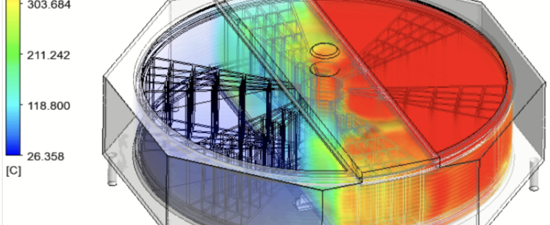
Air preheaters are critical energy-recovery assets integrated into industrial and utility boiler systems to maximize thermal efficiency. Situated in the flue gas exhaust path, these heat exchangers capture residual thermal energy from combustion gases and transfer it to incoming combustion air. By elevating the temperature of the inlet air, air preheaters reduce the amount of fuel required to maintain boiler temperatures, lowering fuel consumption and minimizing carbon emissions. Computational Fluid Dynamics (CFD) provides thermal and plant engineers with a non-destructive digital laboratory to visualize complex gas flows, assess thermal performance, and eliminate structural degradation with high precision.
Technical and Theoretical Description
From a thermal-fluid perspective, an air preheater operates on coupled multi-mode heat transfer governed by the three-dimensional, compressible Navier-Stokes equations and the energy equation. Whether modeling a recuperative (tubular) or regenerative (rotating matrix) preheater, the system handles two distinct fluid streams: high-temperature, ash-laden flue gas and low-temperature combustion air. Because the high-velocity gases passing through the heat exchanger tubes or baskets are intensely turbulent, CFD simulations utilize advanced turbulence models, most notably the Reynolds-Averaged Navier-Stokes (RANS) Shear Stress Transport (k-omega SST) model to capture adverse pressure gradients, boundary layer separation, and localized swirling.
A primary theoretical focus in air preheater modeling is Conjugate Heat Transfer (CHT), which simultaneously solves the conduction through metal heat-exchanger surfaces and the convection within the fluid streams. Heat transfer is quantified using Fourier’s Law for solid conduction and Newton’s Law of Cooling for convection, where the localized heat transfer coefficient is heavily dependent on boundary layer development. Furthermore, because flue gas carries significant amounts of fly ash, discrete phase modeling (DPM) utilizing Eulerian-Lagrangian tracking is coupled with the flow field. This tracks individual ash particles by applying Newton’s second law, calculating the balance of hydrodynamic drag, gravity, and buoyancy forces to evaluate particle trajectories and localized wall impacts.
Business Value of CFD Implementation
From a commercial viewpoint, deploying CFD to analyze and optimize air preheater performance yields massive capital expenditure (CapEx) savings and directly lowers plant operating expenditures (OpEx). In the design or retrofit phase, CFD serves as a rapid virtual prototyping tool. Engineers can evaluate dozens of tube arrangements, baffle configurations, and sealing geometries in software, compressing the engineering timeline and ensuring optimal thermal effectiveness before manufacturing the physical components.
In terms of OpEx, an optimized air preheater directly drives fuel cost savings. Elevating combustion air temperature by just a few degrees significantly increases overall boiler efficiency, resulting in millions of dollars in annual fuel savings for large-scale power plants. Additionally, CFD helps maximize the operational lifespan of downstream components. By minimizing the pressure drop across the air preheater, the parasitic power consumption of forced draft and induced draft fans is substantially reduced, lowering the plant’s internal electricity usage and maximizing net power output.
Challenges of CFD in Air Preheater Modeling
Despite its analytical power, simulating an air preheater introduces steep multi-scale physical and numerical challenges. The foremost obstacle is the extreme discrepancy in geometric scales. A utility boiler ducting system stretches across tens of meters, yet the boundary layer fluid physics, matrix plate gaps, or fine tube clearances require millimeter-scale mesh resolution. Attempting to fully resolve thousands of individual plates or tubes in a single macro-scale simulation generates an unmanageable mesh count that surpasses typical computational budgets.
Another major hurdle is accurately capturing the non-linear physics of structural degradation, specifically ash fouling, erosion, and cold-end acid condensation. As ash-laden flue gas cools inside the preheater, it can drop below the acid dew point of sulfur oxides, causing sulfuric acid to condense on the metal surfaces. This liquid acid traps fine ash particles, leading to accelerated corrosion and severe ash fouling that plugs flow passages. Modeling this transient, multi-phase phase change alongside chemical condensation rates introduces highly sensitive numerical source terms that are exceptionally prone to instability.
Solutions for High-Fidelity Simulation
To overcome these multi-scale and multi-phase challenges, modern plant engineering workflows deploy specialized numerical simplification techniques and coupled physics solvers. Engineers resolve the geometric scale discrepancies by utilizing porous media approximations or distributed resistance models for the core heat transfer matrix. Instead of meshing every individual plate or tube, the air preheater core is treated as a continuous fluid zone with anisotropic flow resistance and volumetric heat sources calibrated via empirical Nusselt number correlations.
To handle localized degradation mechanisms like ash erosion and fouling, discrete phase models are combined with customized wall-boundary conditions. In regions prone to cold-end corrosion, localized surface temperatures are extracted from the CHT solver and checked against thermodynamic dew-point equations to map acid condensation risks. Finally, to eliminate identified flow maldistributions, engineers use the CFD environment to virtually iterate flow-correcting devices, such as introducing turning vanes, mixing plates, or optimized duct geometries. Validating the performance of these modifications in software guarantees uniform gas distribution, eliminating cold spots and ensuring a highly reliable, low-maintenance thermal blueprint.
Author: Caesar Wiratama
Find me on Linkedin