
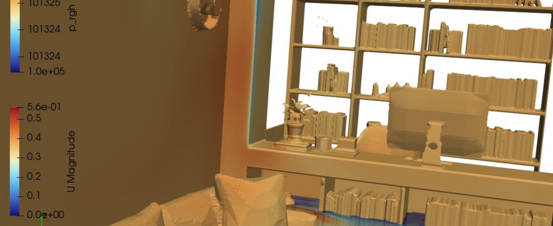
HVAC systems in residential and commercial rooms are primary assets responsible for maintaining thermal comfort, protecting indoor environmental quality, and minimizing energy expenditure. Designing a room’s climate control system is a delicate balancing act: air must be conditioned and distributed effectively to satisfy human occupancy, but improper air diffuser placement or unoptimized velocity settings lead to immediate liabilities. These include chilly drafts blowing directly onto occupants, stagnant hot zones in room corners, and excessive vertical temperature differences. Computational Fluid Dynamics (CFD) provides building services and indoor environmental engineers with a precise digital laboratory to visualize localized air distribution, analyze temperature fields, and maximize thermal comfort with high fidelity.
Technical and Theoretical Description
From a building physics perspective, room climate control operates on coupled, forced-plus-natural (mixed) internal convection and multi-mode heat transfer governed by the three-dimensional, compressible Navier-Stokes equations and the energy equation. Air circulation is driven by mechanical supply diffusers—such as ceiling grilles, linear slots, or wall units—that introduce conditioned air into the room, where it interacts with buoyancy-driven thermal plumes rising from heat sources like electronic equipment, lighting, and human occupants. To resolve these opposing flow regimes and accurately capture near-wall boundary layers, CFD simulations utilize advanced turbulence closures, most notably the Reynolds-Averaged Navier-Stokes (RANS) Shear Stress Transport (k-omega SST) or Realizable k-epsilon models due to their stability in tracking flow separation and air jet detachment.
The core theoretical focus in room modeling centers on evaluating indoor thermal comfort via a conjugate heat transfer (CHT) framework. Heat transfer through the building envelope—such as conduction through multi-layered insulated walls or solar radiant heat gain through glass windows—is solved using Fourier’s Law and the Discrete Ordinates (DO) radiation model. The computed localized air velocity and temperature fields are directly processed through empirical plain-text mathematical formulas to calculate the core metrics established by international standards like ASHRAE Standard 55 and ISO 7730:
- PMV (Predicted Mean Vote): Predicts the average thermal sensation scale (from -3 for too cold to +3 for too hot) for a large group of occupants based on localized air temperature, airspeed, relative humidity, mean radiant temperature, clothing insulation, and metabolic rate.
- PPD (Predicted Percentage of Dissatisfied): Establishes a quantitative statistical percentage of occupants who will feel thermally uncomfortable in the space.
- ADPI (Air Diffusion Performance Index): Evaluates the percentage of the occupied zone where the localized air velocity is under 0.35 meters per second and the effective draft temperature falls within a comfortable range, ensuring uniform air mixing without localized drafts.
Business Value of CFD Implementation
From a commercial viewpoint, deploying CFD to analyze and refine room HVAC layouts yields substantial capital expenditure (CapEx) savings and directly lowers ongoing operational expenditures (OpEx). Historically, mechanical engineers relied on conservative, rule-of-thumb calculations, resulting in the over-specification and procurement of oversized air handling units, ductwork, and chillers. CFD acts as a rapid virtual prototyping tool during the architectural planning or renovation phase, enabling design teams to determine the minimum cooling and heating capacity required to maintain comfort under peak thermal loads, effectively right-sizing the mechanical equipment and cutting upfront procurement costs.
In terms of OpEx, a CFD-optimized climate control layout directly slashes monthly electricity bills and enhances occupant well-being. For commercial offices and real estate developers, indoor thermal comfort is directly linked to occupant satisfaction and workforce productivity; localized hot spots or freezing drafts cause frequent employee complaints and decrease cognitive performance. CFD optimization ensures that air is distributed uniformly, eliminating draft risks and thermal stagnation. This uniform distribution allows facility managers to safely raise cooling setpoints or lower heating setpoints by a few degrees without compromising comfort, yielding substantial annual utility savings and maximizing the commercial value of the real estate asset.
Challenges of CFD in Room Comfort Modeling
Despite its analytical power, simulating room thermal comfort introduces distinct physical and numerical scale challenges. The foremost obstacle is the extreme spatial density of highly variable thermal boundaries and micro-scale flow obstructions. Within a standard room, high-intensity heat sources like a desktop computer or a human body sit directly adjacent to cold windows, while the flow field is further obstructed by furniture, partition walls, and lighting fixtures. Meshing these disparate elements while resolving thin thermal boundary layers requires a highly strategic grid layout to prevent the computational cell count from swelling excessively.
Another major hurdle is characterizing the transient, dynamic nature of real-world environments. Room load profiles are highly erratic; a room can instantly transition from completely vacant to densely populated, causing metabolic heat and carbon dioxide levels to surge within minutes, while solar radiation patches crawl across the floor throughout the day. If a simulation oversimplifies these inputs into static daily averages, it completely misses transient thermal lagging and localized temperature pooling. Furthermore, modeling buoyancy-driven flows under low-velocity conditions requires a highly stable pressure-velocity coupling mechanism; any minor numerical imbalance in the gravity-density source term can introduce unphysical numerical velocities, ruining the validity of the comfort predictions.
Solutions for High-Fidelity Simulation
To overcome these spatial complexity and transient load challenges, modern mechanical engineering workflows combine advanced spatial discretization with smart boundary automation. Engineers resolve geometric scale discrepancies by utilizing high-quality body-fitted polyhedral or hex-dominant meshes. Heavy grid refinement and tight prism layer inflation are concentrated around the supply diffusers, return grilles, and near human boundaries to perfectly capture thin thermal boundary layers and localized velocity gradients. Real-world weather data and changing solar positions are automated using time-dependent profile tables or customized user-defined functions (UDFs) that update boundary conditions hour by hour.
To handle human thermal interactions accurately, occupants are modeled using realistic thermal manikins that account for convective and radiative heat loss from the skin, capturing the natural upward thermal draft (the human micro-plume) that carries air up into ceiling extraction zones. Finally, to eliminate identified drafts or stagnant zones, engineers use the CFD environment to virtually iterate design corrections. This includes shifting diffuser positions, switching from traditional mixing ventilation to low-velocity displacement ventilation panels, or fine-tuning thermostat control loops. Validating the success of these modifications in software guarantees an energy-efficient, responsive, and perfectly comfortable indoor environment before a single piece of physical ductwork is fabricated.
Author: Caesar Wiratama
Find me on Linkedin