
Introducing the tensorSTHE-ThermalShell Template
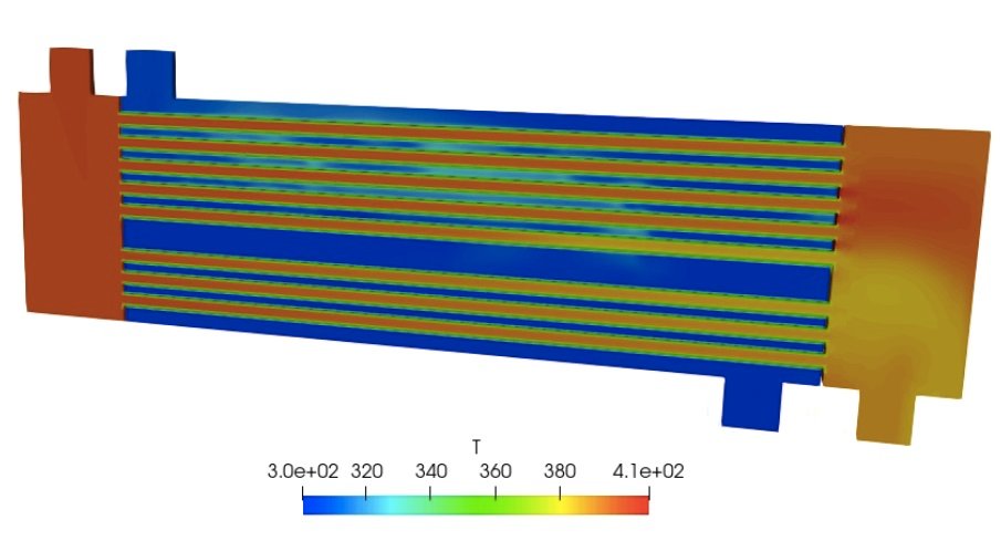
The tensorSTHE-ThermalShell template is a specialized folder within this project designed specifically for simulating shell-and-tube heat exchangers. Instead of forcing you to build a heavy, complex 3D grid for the solid metal walls, this template uses a smart “thermal shell” shortcuts feature. It splits your simulation into just two regions—the hot fluid stream and the cold fluid stream—and calculates the metal wall’s thermal resistance using a mathematical 1D conduction layer. This saves massive amounts of computer memory while delivering accurate heat transfer predictions. If you use this specific template for your work, all that is asked is that you mention and give credit to tensorSTHE-ThermalShell in your reports or projects.
How the Fluid Streams are Arranged
The template sets up a classic counter-flow heat exchanger using liquid water as the default fluid for both sides. The hot fluid stream enters the tube side at one end and exits at the other, starting at a default temperature of 353 Kelvin. Meanwhile, the cold fluid stream enters the shell side through an intake nozzle at 300 Kelvin and flows in the opposite direction. The software automatically tracks the heat crossing the thin interface wall while logging the final outlet temperatures and overall wall heat flux.
How to Run Your First Simulation
Running the simulation is handled through four simple terminal commands. First, you run a mesh pipeline command, which automatically combines your 3D shapes, isolates the hot and cold fluid zones, and restores the fresh physics folders. Second, you launch the actual solver script to split the math across multiple computer processors and start the calculation. Third, a reconstruction script safely merges all the split processor data back together once the run finishes. Finally, a cleanup script is available to wipe away old logs and grid data whenever you want a fresh start.
Adjusting Operating Conditions and Temperatures
Changing your basic operational settings is incredibly easy and does not require digging through complex sub-folders. You can open a single, centralized settings file to change target variables like mass flow rates, inlet temperatures, fluid density, and reference pressure. To change the physical properties of the heat exchanger itself, you can easily open the temperature boundary file to type in a new wall thickness or change the thermal conductivity material constant (which defaults to standard stainless steel).
Changing the 3D Heat Exchanger Shape
To swap in your own custom heat exchanger design, you drop your new 3D files into the geometry folder using standard .stl shapes scaled in meters. For the automated grid tool to split the fluid streams correctly, you must update two coordinate points in the setup files: one target point must sit safely inside the tube fluid volume, and the other must sit inside the shell fluid volume. Make sure your virtual background wind-tunnel box is slightly larger than your new 3D model so no edges are cut off, then rerun the mesh script from scratch to bake in the new hardware layout.
A Quick Warning
Please keep in mind that this template is a development version. This means some of the background settings might not be perfectly optimized for every single scenario yet. The accuracy of the final answers depends entirely on your specific setup and shape, so pt-tensor.com does not take responsibility for the final simulation data. Always double-check your engineering results.
Author: Caesar Wiratama
Find me on Linkedin