
Transforming Digital Concepts into Robust Physical Structures
The design process begins with a Detailed CAD Design that serves as the absolute foundation for the entire engineering project. Startups use advanced Computer-Aided Design tools to model the exact physical geometry of the dust collector, including the outer housing, internal baffling, filter cartridges, and the collection hopper. Once this digital blueprint is established, Finite Element Analysis (FEA)
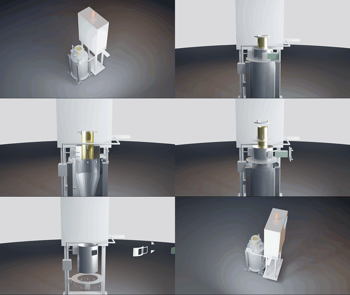
Detailed 3D Design and Conceptual Animation of Dust Collector using FreeCAD and Render in Blender
is applied to test the structure against intense operating conditions. This structural simulation evaluates how the sheet metal handles high vacuum pressures, the heavy weight of accumulated particulate matter, and external forces like wind or seismic activity. By identifying weak points virtually, engineers can strategically reinforce high-stress areas and reduce material thickness where it isn’t needed, saving significant manufacturing costs.
Mastering Airflow Dynamics via Computational Fluid Dynamics
Once the physical shell is validated, the focus shifts to Flow Optimisation Using Computational Fluid Dynamics (CFD). The core efficiency of a dust collector relies entirely on how air moves through the system, making airflow visualization critical. CFD simulations allow engineering teams to map air velocity, pressure drops, and turbulence throughout the internal chambers. By analyzing these virtual air currents, designers can eliminate stagnant “dead zones” where dust might settle prematurely and clog the system. Furthermore, CFD ensures that incoming air is distributed evenly across all filter elements rather than slamming into a single section. This uniform distribution prevents premature filter wear, lowers the total system pressure drop, and drastically reduces the electrical energy required to run the main exhaust fan.
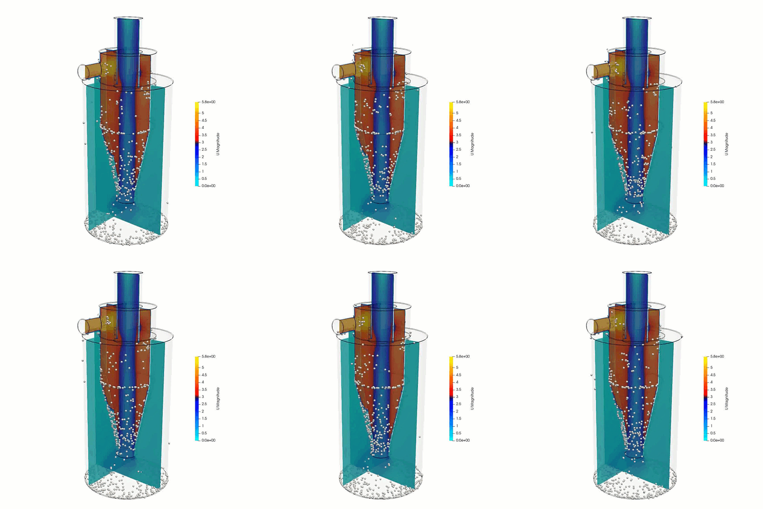
Dust Collector Simulation using OpenFOAM CFD and LIGGGHTS DEM
Predicting Particle Behavior with Discrete Element Method Modeling
To capture the true physical reality of industrial air filtration, engineers must simulate the actual dust particles using the Discrete Element Method (DEM). While CFD maps the behavior of the air, DEM tracks millions of individual solid particles as they move, collide, and interact with the internal walls of the collector. By coupling CFD and DEM into a unified simulation, startups can analyze how different particle sizes, shapes, and densities behave in real time. This allows designers to verify that heavy particles successfully drop out of the airstream into the hopper via gravity, while finer dust travels safely to the filter face. It also highlights high-velocity impact zones prone to abrasive wear, enabling companies to place expensive wear-resistant liners only exactly where they are needed.
Accelerating Market Entry and Minimizing Engineering Risk
Integrating a comprehensive CAE Workflow provides startups and established companies with a massive competitive edge in product development. Relying on physical prototypes for fluid-particle systems is incredibly slow, expensive, and prone to hidden errors that only show up after installation. Virtual testing allows engineering teams to run dozens of design iterations in days rather than months, perfecting the equipment before manufacturing begins. Ultimately, leveraging these advanced simulation tools eliminates catastrophic field failures, cuts development budgets in half, and empowers smaller companies to launch highly optimized, energy-efficient industrial products that rival established market leaders.
Author: Caesar Wiratama
Find me on Linkedin