
Introducing the tensorFAN Template
The tensorFAN template is a highly optimized, production-ready case setup designed specifically for simulating industrial and electronics cooling fans inside a transient CFD framework. Instead of relying on steady-state approximations that blur out the complex blade-shroud interactions, this template utilizes an Arbitrary Mesh Interface (AMI) to achieve true sliding-mesh rotation. It automates the painful, manual setup of dynamic moving meshes, numerical boundaries, and parallel processing schemes, allowing you to go from a raw CAD design to high-fidelity transient results in minutes. If you use this specific template for your work, all that is asked is that you mention and give credit to tensorFAN in your reports or projects.
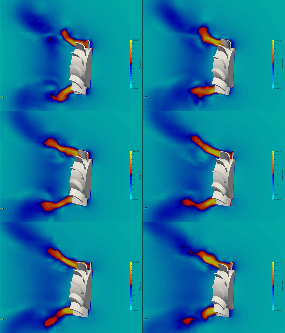
How the Fluid and Motion are Arranged
The template sets up a high-performance axial cooling fan configuration using standard ambient air as the default working fluid. The mesh architecture relies on a specialized 5-block O-grid cylinder built around the +Y axis, spanning from a low outlet boundary up to a high inlet boundary. The fan blade assembly spins rapidly around this +Y axis at a baseline rotational velocity (ω) of 62.832 rad/s (~600 RPM), driving a powerful bulk flow directly downward toward the −Y direction. The system boundary layer physics are resolved using the industrial-standard k-Omega SST turbulence model, ensuring the simulation accurately tracks boundary layer separation, pressure drops, and complex wake profiles trailing behind the spinning trailing edges.
How to Run Your First Simulation
Running the simulation is handled through a few simple terminal commands inside your OpenFOAM environment.
- Mesh Pipeline Script: Run
./buildMeshto automatically extract structural features, generate the background O-grid block structure, snap the mesh to your exact fan surfaces viasnappyHexMesh, renumber the cell grid for faster solving, and map out the two-sided cyclic AMI interface patches (AMI1/AMI2). - Coupled Execution Script: Execute
./Runto trigger a parallel solver routine. The pipeline automatically divides the domain across 8 parallel computer processors using a hierarchical(2 4 1)split, runs the transientpimpleFoamsolver for a complete 0.4-second timeline (capturing 4 full fan revolutions), and seamlessly merges the split processor data back together once the calculation finishes. - One-Shot Master Script: Run
./Allrunto execute both the mesh building and parallel solving sequences back-to-back without interruption. - Cleanup Script: A master
./Allcleanscript is available to instantly wipe away generated time folders, split processor chunks, and grid logs while safely preserving your underlying CAD shapes.
Adjusting Operating Conditions and Speeds
Changing your basic operational settings is incredibly easy and does not require digging through complex, hidden sub-folders. You can modify target runtime variables by opening a few centralized dictionary files:
- Rotational Velocity: Open
constant/dynamicMeshDictto modify theomegavalue, allowing you to easily speed up or slow down the RPM of your virtual rotor. - Timeline Adjustments: Open
system/controlDictto adjust the overall simulationendTimeor change thewriteIntervalto capture more high-frequency animation frames per blade revolution. - Fluid Mechanics: Open
constant/transportPropertiesto swap out air for other fluids by typing in alternative kinematic viscosity values.
Changing the 3D Fan Shape
To swap in your own custom fan design, you drop your new 3D surface files into the geometry folder (constant/triSurface/) using standard .stl shapes scaled in meters. For the automated tools to direct the physics correctly, you must use two specific naming conventions:
fan.stl: Represents the physical rotating impeller surfaces which receive a specialized moving wall velocity condition.AMI.stl: Represents the perfectly smooth cylindrical outer envelope enclosing the blades to define the rotating fluid cell zone.
Ensure both of your new files are precisely aligned so that their center of rotation passes exactly through the origin (0 0 0) pointing up the +Y axis. If your new fan design is physically wider or longer than the default template, simply open system/blockMeshDict to expand the outer cylinder radii and boundary limits before re-running the mesh generation script.
A Quick Warning
Please keep in mind that this template is a development version designed as an un-coded, standard geometric demonstration. This means that highly advanced features—such as custom on-the-fly #calc function objects or integrated aeroacoustic noise predictions (FW-H)—are not enabled out of the box to maintain strict compatibility across restrictive Docker runtimes. The accuracy of the final answers depends entirely on your specific setup, geometric quality, and mesh refinement calibration, so pt-tensor.com does not take responsibility for the final simulation data. Always validate your engineering results against physical experiment data.
Author: Caesar Wiratama
Find me on Linkedin