
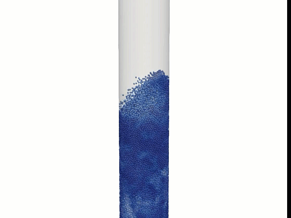
In heavy chemical processing and thermal power industries—spanning petroleum refining, plastics manufacturing, biomass gasification, and metallurgical roasting—the fluidized bed reactor is a premier asset for ultra-high-efficiency mass and heat transfer. By forcing a pressurized gas or liquid upward through a dense bed of solid particulate matter, the system transforms a static heap of rocks or catalyst particles into a dynamic, boiling fluid analogue. The resulting state maximizes particle-fluid contact area, creating a highly isothermal, intensely mixing chemical engine.
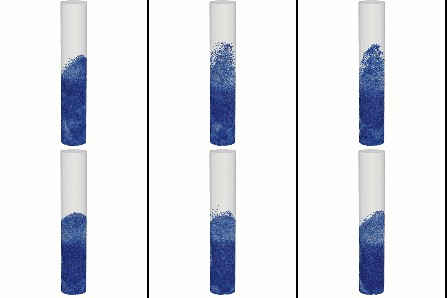
Operating a fluidized bed efficiently requires maintaining a stable fluidization regime—specifically targeting the precise window between the minimum fluidization velocity (Umf) and the terminal entrainment velocity (Ut)—while strictly minimizing localized gas channeling and severe wall erosion. Because uniform temperature control directly dictates chemical conversion rates and limits hazardous thermal runaway, engineering teams rely heavily on advanced multiphase simulation tools to optimize gas distributor grids, calculate heat exchanger tube placement, and predict bubble dynamics.
However, simulating a fluidized bed is an exceptionally deceptive, highly chaotic multi-scale hydrodynamics challenge. The internal flow field operates under a violent, transient regime where gas and solids continuously form mesoscale structures like bubbles, clusters, and dense emulsions that change shape within milliseconds. If your simulation framework relies on simplified homogenous continuum models or defaults to static grid architectures, your solver will suffer from smeared phase boundaries and false chemical conversion rates—leaving your design team with highly inaccurate efficiency maps.
1. The Physics Anchor: Eulerian-Granular Modeling and the Fluidization Transition
The multi-phase granular hydrodynamics inside a fluidized bed are governed by a dual Eulerian-Eulerian or Eulerian-Lagrangian framework tightly coupled with kinetic theory of granular flow (KTGF). The material behavior maps a highly non-linear physical sequence:
- The Hydrodynamic Regime Topology: As upward gas velocity increases, the drag force exerted on individual solid particles grows. At the critical minimum fluidization velocity (\(U_{mf}\)), the pressure drop across the bed exactly balances the gravitational weight of the solid inventory. Beyond this point, the continuous bed expands, and excess gas pockets coalesce into distinct bubbles that rise rapidly through a dense emulsion phase. This creates a classic core-annulus flow structure: a high-velocity, low-density upward bubble stream along the central axis balanced by a dense, slow-moving downward slurry of solids hugging the outer perimeter.
- The Inter-Particle Contact Mechanics: To track this computationally without modeling billions of individual grains explicitly, high-fidelity solvers treat the solid phase as an interpenetrating continuum using an Eulerian-Granular approach. The solid phase properties—such as granular pressure, viscosity, and conductivity—are modeled using KTGF, which adapts the classical kinetic theory of gases to macro-particles. This mathematical formulation calculates the microscopic kinetic energy of particle fluctuations (known as granular temperature), allowing the solver to capture the intense dissipative shear forces and dampening effects that occur during violent multi-phase churning.
2. Industry Context: Where Fluid Phase Contact Controls Chemical Conversion
Optimizing distributor plate profiles and managing gas-solid contact times through high-fidelity multi-phase simulations directly dictates the chemical yield, thermal efficiency, and environmental compliance of industrial facilities:
- Refinery Fluidized Catalytic Cracking (FCC) Units: Refineries utilize massive circulating fluidized beds (CFBs) to crack heavy oil fractions into high-value gasoline. Highly turbulent gas-solid contact allows the vaporized oil to react with hot catalyst microspheres instantly. Engineers deploy multi-phase reactive CFD to ensure uniform catalyst distribution, preventing “cold spots” that lower conversion efficiency and “hot spots” that permanently deactivate the expensive catalyst matrix.
- Fluidized Bed Combustion (FBC) Power Plants: Power generation facilities burn low-grade coal, biomass, or municipal waste within a fluidized bed of hot limestone. The intense mixing allows for complete combustion at significantly lower temperatures than conventional pulverized furnaces, which inherently suppresses the formation of harmful nitrogen oxides (NOx). Furthermore, the limestone directly absorbs sulfur dioxide (SO₂) in-situ, eliminating the need for downstream flue-gas desulfurization infrastructure.
- Gas-Phase Polyethylene Reactors: In plastics manufacturing, ethylene gas is passed through a fluidized bed of catalyst particles to grow polymer chains. Because polymerization is a highly exothermic reaction, any localized failure in fluidization can cause the plastic powder to melt, fuse, and form a massive solid block of polymer (known as “sheeting”) inside the vessel. Engineers simulate gas-distribution dynamics to guarantee uniform cooling, keeping the reactor continuously online.
3. The Traps & Friction: Why Fluidized Bed Simulations Fail
Predicting the exact bubble distribution and real-world chemical conversion inside a high-speed bubbling chamber requires avoiding severe numerical and physical traps:
- Relying on Generic Sub-Grid Drag Models: The most common and destructive pitfall in fluidized bed modeling is defaulting to standard, macro-scale drag formulations like the Gidaspow or Wen-Yu models without sub-grid corrections. These standard models assume that particles are uniformly distributed throughout a computational mesh cell. In reality, sub-grid scale structures like sub-millimeter particle clusters form naturally, allowing gas to slip around them with vastly reduced drag. Skipping sub-grid scale filtering (such as the Energy-Minimization Multi-Scale, or EMMS, model) causes the solver to drastically over-predict drag, outputting an unphysically expanded, over-fluidized bed that completely miscalculates chemical residence time.
- Utilizing Steady-State Solvers for Transient Bubble Dynamics: To accelerate engineering turnarounds, teams frequently attempt to solve fluidized beds using steady-state multi-phase approximations. However, fluidization is an intrinsically chaotic, time-dependent phenomenon dominated by bubble eruption, splashing at the bed surface, and continuous vortex shedding. A steady-state approach flattens this transient behavior, treating a violently oscillating bubbling bed as a smooth, static density gradient. This artificial smoothing completely fails to capture the true mass-transfer limitations caused by large, bypassing gas bypass bubbles.
- Using Coarse Meshes Relative to the Particle Clustering Scale: The highest gradient changes in phase volume fraction and gas velocity occur at the sharp boundaries between rising bubbles and the surrounding dense emulsion. If your volume grid mesh size is significantly larger than these mesoscale structures, the mathematical solver suffers from severe numerical diffusion, artificially blending the phases together. Without a highly refined mesh or dynamic grid adaptation capable of resolving micro-scale structural clusters, your simulation will completely miscalculate the reactor’s total chemical yield and pressure drop.
4. Conquering the Bubbling Multiphase Boundary
A beautiful color contour plot showing volumetric gas distribution is completely useless if your digital product yield curves do not correlate with physical plant telemetry. Validating your fluidized bed simulation pipeline requires moving past uncorrected isotropic continuum shortcuts and deploying transient, density-coupled Euler-Granular workflows or discrete Euler-Lagrangian (DEM-CFD) methodologies that naturally handle discrete cluster dynamics.
Your simulation parameters must be cross-referenced against empirical laboratory and field metrics—such as real-time differential pressure fluctuations across the bed height, fiber-optic needle probe density profiles, and radioactive particle tracking (RPT) validation data—ensuring your non-linear sub-grid drag parameters, real-world geometries, and transient bubble-coalescence paths perfectly reflect physical industrial processing boundaries.
Author: Caesar Wiratama
Find me on Linkedin