
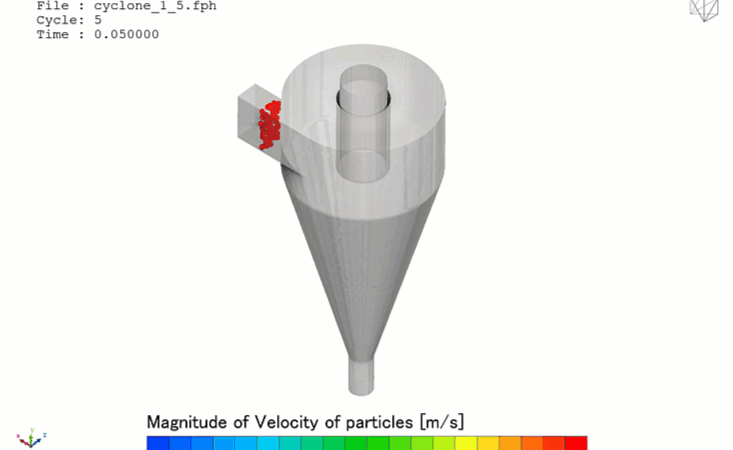
In heavy processing industries—spanning mining and mineral processing, cement manufacturing, chemical refining, and sawdust or agricultural collection lines—the cyclonic particle separator (or gas cyclone) is a premier asset for gas-solid isolation. By forcing a particle-laden gas stream tangentially into a cylindrical-conical chamber, the device creates a high-intensity, unforced double-vortex fluid engine. The centrifugal forces sling heavy solid particles radially outward against the cyclone wall where they slide down to a collection hopper, while the cleaned gas turns sharply to exit upward through a central vortex finder tube.
Operating a cyclonic separator efficiently requires maximizing collection efficiency—specifically targeting a precise 50% cut-point particle diameter (d50)—while strictly minimizing the mechanical pressure drop across the stage. Because high pressure drops drive up fan or compressor power draw, engineering teams rely heavily on Computational Fluid Dynamics (CFD) to optimize vortex finder insertion depths, calculate cone tapering angles, and design customized inlet scrolls.
However, simulating a cyclonic particle separator is an exceptionally deceptive, highly anisotropic turbomachinery challenge [dataviz]. The internal flow field operates under an aggressive, swirling vortex core where fluid velocities span from subsonic to near-stationary within millimeters. If your simulation framework relies on simplified steady-state approximations or defaults to standard isotropic turbulence models, your solver will suffer from smeared particle plumes and false cut-points—leaving your design team with highly inaccurate efficiency maps.
1. The Physics Anchor: Eulerian-Lagrangian Tracking and the Rankine Vortex Discontinuity
The multi-phase granular fluid dynamics inside a gas cyclone are governed by a dual Eulerian-Lagrangian framework tightly coupled with anisotropic turbulence formulations. The fluid behavior maps a highly non-linear physical sequence [dataviz]:
[Gas Enters Tangentially] ➔ [Forms Descending Outer Helical Vortex] ➔ [Angular Velocity Spikes Inward via Angular Momentum Conservation] ➔ [Rankine Vortex Core Shifts Flow Upward] ➔ [Solid Particle Inertia Decouples From Streamlines]
- The Rankine Vortex Topology: The continuous gas phase forms a classic Rankine vortex, blending a free vortex region on the outer perimeter (where velocity decreases as radius increases) with a solid-body forced vortex core at the central axis (where velocity decreases to zero). To capture this mathematically, the solver must resolve extreme radial pressure gradients that pull the gas inward while centrifugal forces push it out.
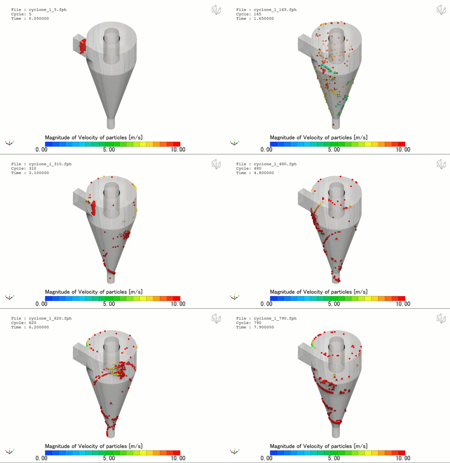
- The Particle Inertia Decoupling: The entrained solid particles are tracked individually or in packets as Lagrangian elements exchanging momentum with the gas phase. As the gas spirals downward and hits the Rankine core interface, it makes a sharp, 180-degree vertical turn to exit through the vortex finder. Because the solid particles possess significantly higher density and inertia, they fail to track these tight, twisting fluid streamlines. They decouple from the flow and slam directly into the outer conical wall, sliding into the lower discharge lock.
2. Industry Context: Where Airflow Separation Secures Plant Infrastructure
Optimizing internal cyclone profiles and managing particle-split curves through high-fidelity multi-phase CFD directly dictates the environmental compliance, capital longevity, and energy foot-prints of heavy industrial facilities:
- Refinery Fluidized Catalytic Cracking (FCC) Cyclones: Refineries utilize internal high-temperature cyclones to separate abrasive catalyst particles from product vapor streams. Engineers deploy erosion-coupled CFD to ensure the abrasive catalyst fines do not grind through the cyclone’s metal walls, preventing an unscheduled, multi-million-dollar refinery shutdown.
- Industrial Cement Kiln Preheater Towers: Cement manufacturing requires routing raw meal dust through multiple stages of suspension preheater cyclones. Engineers use CFD to maximize dust capture rates, ensuring the hot gases transfer heat into the solid particles at maximum thermal efficiency before the material enters the firing kiln.
- Wood Processing Dust Collection Systems: High-throughput sawmill and cabinetry shops require continuous sawdust evacuation. Designers use detailed cyclone simulations to maximize collection efficiency for fine, non-spherical wood fibers, ensuring the air returned to the factory floor complies with tight industrial health and safety standards.
3. The Traps & Friction: Why Cyclonic Separator CFD Fails
Predicting the exact particle cut-point and real-world pressure drop inside a high-speed swirling chamber requires avoiding severe numerical and physical traps:
Relying on Standard Isotropic Two-Equation Turbulence Models
The most common and destructive pitfall in cyclonic CFD is defaulting to standard, isotropic two-equation turbulence models like the standard k-epsilon or standard k-omega SST formulations. These models are hardcoded to assume that turbulence is uniform in all directions. In a highly swirling cyclone, the severe axial rotation creates anisotropic turbulence that dampens radial velocity fluctuations near the core. An isotropic model will over-predict turbulent viscosity, artificially dampening the tangential velocity peak, predicting a weak, sluggish vortex that completely miscalculates the particle collection efficiency.
Utilizing Steady-State Solvers for Transient Vortex Meandering
To minimize processing times across large layout models, engineers frequently attempt to run cyclone simulations using steady-state solvers. However, the internal Rankine vortex core is never physically stationary; it undergoes a highly transient, time-dependent oscillating motion known as vortex core meandering. This meandering acts as a continuous fluid mixer that can re-entrain separated particles back into the ascending clean gas stream. A steady-state approach flattens this chaotic behavior, smoothing over the re-entrainment loss and outputting overly optimistic particle capture curves.
Using Coarse Meshes in the Core Boundary Layer and Vortex Finder Lip
The highest shear layers and velocity transitions occur in a sub-millimeter zone directly adjacent to the bottom edge (lip) of the vortex finder tube. If your volume grid mesh is too coarse around this sharp geometric boundary, the mathematical solver will suffer from severe numerical diffusion, artificially smoothing out the local velocity peaks. Without micro-scale prism layer grid refinement tracking the solid walls paired with a robust anisotropic turbulence or scale-resolving model, your simulation will completely miscalculate the separator’s permanent pressure loss.
4. Conquering the Swirling Multi-Phase Boundary
A beautiful color velocity contour plot of an industrial cyclone is completely useless if your digital grade efficiency curves do not correlate with physical plant telemetry. Validating your cyclonic separator CFD pipeline requires moving past isotropic steady-state shortcuts and deploying transient, density-coupled scale-resolving workflows, such as Large Eddy Simulation (LES) or advanced Reynolds Stress Models (RSM) that naturally handle anisotropic rotation.
Your simulation parameters must be cross-referenced against empirical laboratory and field metrics—such as real-time differential pressure transducer data across the inlet-outlet flanges and fractional efficiency weight logs validated on physical scaled wind-tunnel test rigs—ensuring your non-linear particle drag parameters, real-world geometries, and transient core-meandering structures perfectly reflect physical industrial processing boundaries.
Author: Caesar Wiratama
Find me on Linkedin