
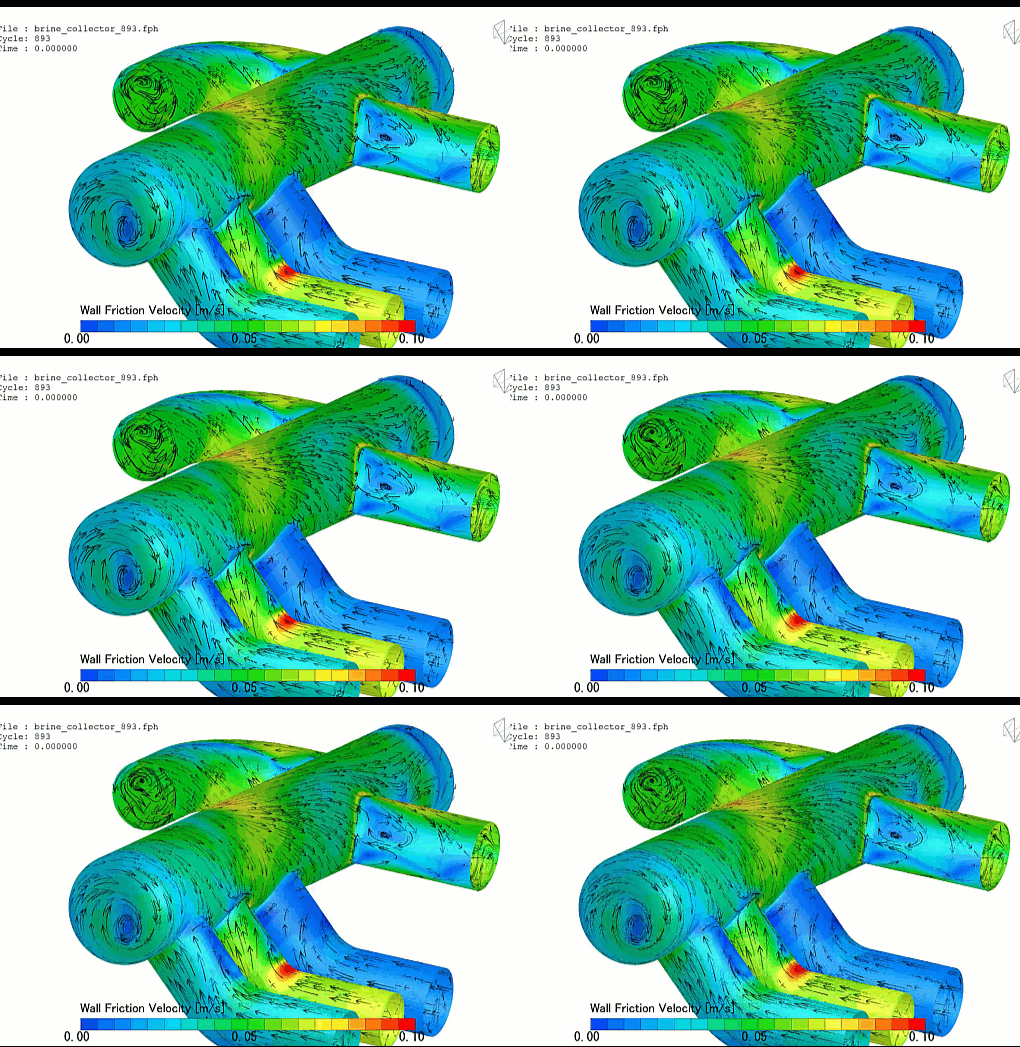
In industrial desalination, zero-liquid-discharge (ZLD) systems, and solution mining operations, the brine collector network is the primary sub-surface or multi-channel header assembly tasked with capturing and evacuating dense, highly concentrated salt solutions. Whether configured as a perforated marine intake-discharge manifold, an under-bed drainage lateral array in a solar evaporation pond, or an internal collector header inside a multi-stage flash (MSF) evaporator, its core engineering objective is identical: to maximize volumetric collection uniformity while strictly managing frictional pressure drops.
Operating a brine collector network efficiently requires achieving a perfectly balanced extraction profile across the entire length of the system. Because brine processing handles fluids packed with dissolved solids running near saturation limits, engineering teams rely heavily on Computational Fluid Dynamics (CFD) to optimize lateral perforation diameters, calculate header tapering angles, and track localized flow velocities.
However, simulating a brine collector is an exceptionally deceptive, highly non-linear multi-phase fluid mechanics challenge. Brine is not a uniform fluid; its local density and viscosity shift dynamically based on salt concentration and temperature. If your simulation framework relies on simplified, uniform density shortcuts or flattens the porous gravel/sand bed into a smeared macro-scale block, your solver will completely miss localized flow starvations—leaving your engineering design team blind to efficiency-killing density stratification and severe scaling traps.
1. The Physics Anchor: Concentration-Dependent Viscosity and Buoyancy-Driven Stratification
The fluid dynamics inside a sub-surface or open-channel brine collector are governed by the multi-component species transport and Navier-Stokes equations, which are tightly coupled with non-linear Concentration-Dependent Density and Viscosity profiles.
As the dense fluid moves through the surrounding media or lateral ports, it exhibits highly complex, non-uniform flow topologies:
[High Salt Concentration Formed] ➔ [Localized Fluid Density and Viscosity Skyrocket] ➔ [Brine Settles into Low-Velocity Floor Pools] ➔ [Density Stratification Discharges Fluid From Collector Eye] ➔ [Localized Salt Crystallization and Scaling Failure]
- The Gravity-Driven Stratification: High-concentration brine possesses a significantly higher density than brackish water or standard seawater. When this fluid enters a collector manifold, gravity forces the dense solution to drop, creating a severe buoyancy-driven stratification. The heavy brine forms a stagnant, sluggish floor layer along the bottom of the collector pipes, while lighter fluids glide over the top, completely disrupting the intended uniform extraction matrix.
- The Porous Pressure Friction (The Ergun Boundary): When collecting brine from an under-bed gravel matrix or sand layer, the aerodynamic and fluidic pressure drop is governed by the Ergun equation. Because high-concentration brine exhibits elevated dynamic viscosity, the viscous resistance term dominates. If the local extraction velocity is poorly distributed, the fluid stalls within the porous bed, driving the local concentration past the saturation threshold and triggering immediate salt crystallization.
2. Industry Context: Where Flow Balance Suppresses Capital Depreciation
Optimizing collector pipe manifolds and maximizing extraction profiles through high-fidelity multi-component CFD directly dictates the environmental footprint, energy consumption, and equipment uptime of massive process plants:
- Sea Water Reverse Osmosis (SWRO) Co-Location Discharge: SWRO plants reject massive streams of highly concentrated brine back into the marine ecosystem. Engineers use multiphase CFD to design offshore diffuser-collector arrays, optimizing nozzle inclination angles to ensure the heavy brine plume dilutes rapidly into ambient cross-flows, preventing toxic hyper-saline pooling on the seabed.
- Solution Mining and Evaporation Pond Harvesting: In potash or lithium extraction operations, subsurface collector laterals pump heavy brine from expansive solar ponds. CFD allows logistics teams to design variable-aperture collector lines, ensuring the pump draw is identical at the furthest node as it is near the wet-well intake, eliminating localized pond dry-outs.
- Multi-Stage Flash (MSF) Distillation Internals: MSF evaporators operate under deep vacuum conditions where flashing brine passes through internal mist eliminators and collection trays. Engineers deploy transient multi-phase simulations to prevent vapor-liquid entrainment, ensuring the collected concentrated brine does not short-circuit into the pure distillate line.
3. The Traps & Friction: Why Brine Collector CFD Fails
Predicting the exact flow path and scaling locations inside a high-salinity processing header requires avoiding common computational shortcuts. Defaulting to standard industrial setups leads to three severe traps:
Utilizing a Constant, Homogeneous Fluid Density Profile
The most common and destructive pitfall in brine collector CFD is configuring the solver with a constant, uniform fluid density and viscosity based on average tank specs. When a simulation ignores concentration-velocity coupling, it predicts a clean, perfectly symmetrical extraction loop across every lateral port. In reality, because of viscosity spikes in high-concentration zones, the fluid encounters vastly superior flow resistance. A simplified model smooths over these localized fluid dampings, failing to alert your design team to severe port starvations that cause real-world headers to perform far below spec.
Relying on Smeared Porous Media Block Shortcuts for Lateral Ports
To save on massive computational cell counts across wide drainage fields, engineers frequently model perforated collector lines by treating the pipe wall and surrounding gravel as a uniform, smeared Porous Medium block. While this shortcut can approximate global pressure drops, it completely flattens the local geometry. A simplified porous model fails to resolve the discrete high-shear fluid jets and toroidal vortices that form as fluid forces its way through individual, sub-centimeter perforation holes. This numerical smoothing under-predicts the localized shear stress, hiding early signs of localized salt precipitation.
Ignoring the Feedback Loop: Mineral Scaling and Fouling Accumulation
As brine moves through a collector port, localized pressure drops can cause dissolved minerals (such as calcium sulfate or sodium chloride) to drop out of solution and bind to the pipe edges. This mineral scaling physically narrows the port diameter, which increases local velocity, alters the pressure drop, and pushes the stagnation zone further down the header. A static, clean-pipe CFD model is entirely blind to this. To build a reliable simulation, engineering teams must deploy transient deposition and fouling models that dynamically deform the fluid mesh in real-time response to calculated chemical precipitation rates.
4. Conquering the High-Salinity Processing Boundary
A stunning color velocity contour plot of a collector manifold layout is completely useless if your digital discharge metrics and pressure-loss logs do not correlate with physical facility logs. Validating your brine collector CFD pipeline requires moving past single-phase shortcuts and deploying transient, density-coupled multi-component workflows. These digital models must be cross-referenced against empirical plant metrics—such as differential pressure transducer data across individual laterals, real-time total dissolved solids (TDS) density tracking, and visual borescope scans of scaled internal pipe walls—ensuring your non-linear viscosity curves, porous resistance matrices, and deposition parameters perfectly reflect physical factory boundaries.
Balancing transient multi-component transport, steep concentration-viscosity gradients, and dynamic mesh deformation demands an elite technical workflow. If your engineering design team is facing unexpected pressure drops across a process line, dealing with rapid scaling and plugging of sub-surface drainage laterals, or struggling to minimize environmental hyper-saline pooling to hit strict EPA mandates, bringing in a highly targeted technical extension can bridge the operational gap.
Author: Caesar Wiratama
Find me on Linkedin