
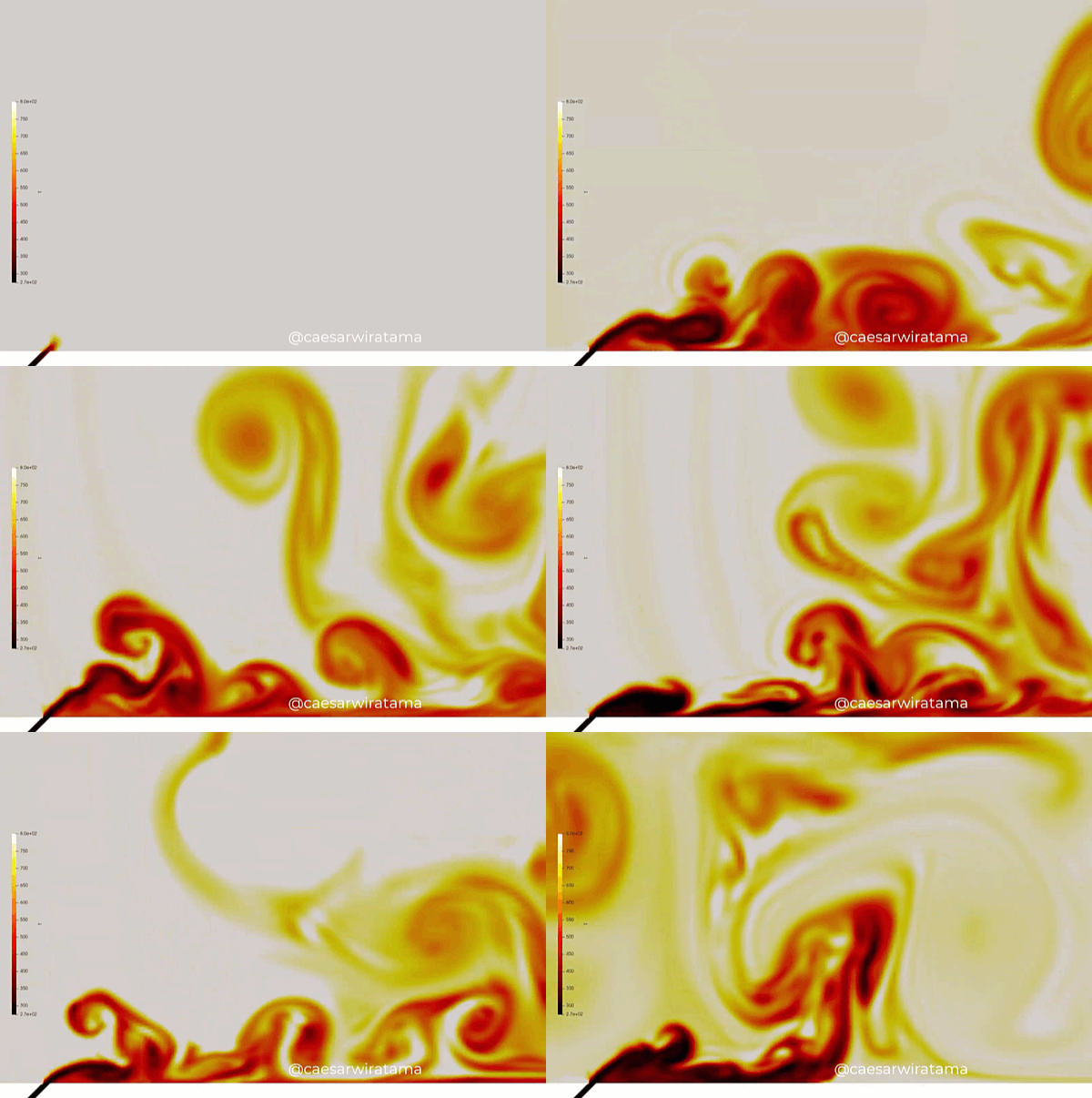
In the development of next-generation gas turbine engines—critical for aerospace propulsion and high-output industrial power generation—thermal safety dictates the physical boundary of engine performance. To maximize thermodynamic efficiency, modern turbines operate at turbine entry temperatures that easily exceed 1,600 degrees Celsius, a thermal threshold far past the metallurgical melting point of the nickel-based superalloy turbine blades.
To prevent the blades from liquefying, engineers deploy a critical thermal shield known as film cooling. By tapping high-pressure bleed air from the compressor stage and routing it through internal cooling channels, the system discharges a continuous, low-temperature fluid stream through a series of micro-holes pitched along the blade surface.
The sole engineering objective of film cooling is to establish a cold, continuous, and insulating fluid blanket that physically isolates the blade metal from the scorching freestream combustion gases.
Evaluating the thermal effectiveness of these cooling grids requires deploying high-fidelity Computational Fluid Dynamics (CFD). However, simulating film cooling is an exceptionally deceptive, highly multi-scale fluid task. It involves modeling micro-scale fluid jets intersecting with a high-velocity, high-momentum cross-flow. If your simulation framework relies on simplified average blowing ratios or flattens these rapid interactions into steady-state formulations, your solver will completely miss localized film blowouts—leaving your design team blind to efficiency-killing turbulent shear lift-off.
1. The Physics Anchor: Counter-Rotating Vortices and Jet Lift-Off Topologies
The fluid dynamics of film cooling are governed by multi-component species and energy transport equations tightly coupled with high-speed Navier-Stokes boundaries. The fluid path transitions rapidly across an aggressive shear layer discontinuity:
[Coolant Discharges From Micro-Hole] ➔ [Encounters Severe Cross-Flow Kinetic Force] ➔ [Forms Counter-Rotating Vortex Pair (CRVP)] ➔ [Vortices Entrain Hot Freestream Gas Underneath Jet] ➔ [Jet Lifts Off Blade Surface]
- The Counter-Rotating Vortex Pair (CRVP): When a cylindrical cooling jet emerges into a high-speed cross-flow, the velocity mismatch between the two fluid streams creates an immediate shear layer. This interaction rolls the coolant jet into a dominant, self-induced structural anomaly known as a Counter-Rotating Vortex Pair.
- The Jet Lift-Off Trap: If the coolant’s injection velocity is too high relative to the freestream (a high blowing ratio), the momentum of the jet overpowers the cross-flow’s tracking capability. The CRVP intensifies, creating a localized aerodynamic lift force. The core of the cooling jet physically lifts off the blade surface.
- The Hot Gas Entrainment Illusion: Once a jet lifts off, the spinning vortices of the CRVP act as a fluid pump. Instead of keeping the blade cool, they actively entrain the scorching hot freestream gas, pulling it underneath the coolant blanket and slamming it directly into the bare metal surface. This creates severe, unpredicted thermal hotspots downstream of the hole.
2. Industry Context: Where Thermal Shielding Delivers Engine Lifespan
Optimizing film cooling hole geometries and maximizing adiabatic cooling effectiveness through high-fidelity CFD directly dictates the structural longevity, thrust limits, and maintenance intervals of advanced propulsion assets:
- Aerospace Jet Engine High-Pressure Turbines: Turbine blades experience extreme centrifugal and thermal stresses. Engineers use CFD to shift from standard cylindrical holes to advanced shaped or fan-shaped cooling holes. Shaped holes diffuse the coolant internally, lowering its exit velocity and momentum to flatten the jet against the blade surface, doubling the local cooling effectiveness.
- Industrial Power Generation Gas Turbines (IGT): Heavy-duty power turbines run continuously for thousands of hours under constant baseline loads. Engineers deploy detailed Conjugate Heat Transfer (CHT) simulations to match external film cooling parameters with internal serpentine rib-roughened cooling channels, ensuring the global blade metal temperature remains strictly uniform to suppress high-cycle thermal fatigue.
- Combustor Liner Thermal Barriers: Combustion chambers feature dense arrays of effusion cooling holes along their internal sheets. CFD allows designers to map how the swirling, highly turbulent flame core interacts with the near-wall coolant layer, preventing localized flame-impingement from burning holes through the structural combustor liner.
3. The Traps & Friction: Why Film Cooling CFD Fails
Predicting the exact adiabatic cooling effectiveness and localized metal temperatures requires navigating strict numerical and modeling traps:
Relying Solely on Steady-State RANS Solvers
To minimize processing times across full blade-passage sectors, engineers frequently simulate film cooling loops using steady-state Reynolds-Averaged Navier-Stokes (RANS) equations paired with standard k-omega SST or k-epsilon turbulence models. While RANS is highly efficient, it is fundamentally incapable of capturing the transient, anisotropic physics of jet-in-cross-flow mixing. RANS artificially stabilizes the fluid fields, “smearing” the transient trailing vortices into a continuous, static cloud. RANS notoriously over-predicts jet lateral spreading and under-predicts the intensity of jet lift-off, outputting overly optimistic cooling effectiveness data that fails during physical engine validation.
Utilizing Simplified Uniform Inlet Velocity Conditions for the Micro-Holes
To save on grid generation labor, a common pitfall is modeling film cooling by slicing a hole onto the blade surface and assigning a uniform, flat velocity inlet boundary condition to that circle. This approach completely ignores the internal plenum and hole-entry aerodynamics. In a real blade, the coolant enters the cooling hole from a narrow internal passage, creating a highly skewed, asymmetric velocity profile at the hole exit. Failing to simulate the entire internal cooling plenum, hole geometry, and external cross-flow simultaneously poisons your entire downstream cooling trajectory dataset.
Under-Resolving the Near-Wall Viscous Sublayer and Thermal Gradients
The ultimate metric of a film cooling simulation is the heat flux entering the solid blade wall. Because the temperature shifts from 600°C (coolant) to over 1600°C (freestream) within a sub-millimeter boundary layer, the grid requires extreme resolution. If your volume mesh is too coarse near the blade surface, the mathematical solver will suffer from massive numerical diffusion, artificially smoothing out the local thermal profiles. Without micro-scale prism layer grid refinement maintaining a strict Wall Y+ near 1, the simulation will completely miscalculate the viscous skin friction and local Nusselt numbers.
4. Conquering the High-Velocity Thermal Boundary
A beautiful, colorful temperature contour plot of a turbine blade is completely useless if your digital adiabatic effectiveness metrics do not correlate with physical test rig logs. Validating your film cooling CFD pipeline requires moving past steady-state shortcuts and deploying fully coupled, transient scale-resolving workflows, such as Large Eddy Simulation (LES) or Detached Eddy Simulation (DES). These digital models must be cross-referenced against empirical laboratory metrics—such as Pressure-Sensitive Paint (PSP) tracking and infrared (IR) thermography datasets validated on physical scaled cascade tunnels—ensuring your anisotropic turbulence fields, vortex structures, and conjugate heat conduction networks perfectly reflect physical physical field boundaries.
Balancing transient high-speed shear layers, multi-scale hole-plenum geometries, and scale-resolving vortex shedding tracking demands an elite technical workflow. If your thermal design team is facing unexpected trailing-edge material erosion during engine tear-downs, dealing with unmanageable coolant consumption that hurts global engine efficiency, or struggling to validate next-generation shaped hole topologies, bringing in a highly targeted technical extension can bridge the operational gap.
Author: Caesar Wiratama
Find me on Linkedin