
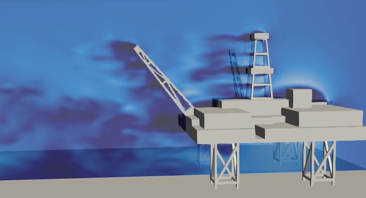
For offshore structural engineers and naval architects, calculating offshore rig wind loads is a critical engineering safety checkpoint. Whether designing a massive semi-submersible platform, a jack-up drilling rig, or a floating production storage and offloading (FPSO) unit, the entire structure must withstand extreme aerodynamic forces during severe ocean storms. Wind loading directly dictates the vessel’s mooring system layout, stability margins, overturning moments, and eventual structural foundation sizing.
Operating a marine asset safely requires mapping out precise wind resistance profiles across all heading angles. Because an offshore topside features a chaotic collection of bluff bodies—including drilling derricks, living quarters, helidecks, crane booms, and pipe racks—engineering teams can no longer rely solely on simplified, static design rules. Modern design validation requires deploying high-fidelity Computational Fluid Dynamics (CFD) to map real-world structural aerodynamics and safeguard ocean assets under extreme wind loads.
However, simulating wind loads across an offshore platform is an exceptionally deceptive bluff-body aerodynamic challenge. Atmospheric wind does not strike a rig as a clean, uniform fluid stream; it acts as a highly turbulent, velocity-sheared boundary layer. If your simulation setup relies on simplified, flat projected areas or flattens these rapid transient eddies into a steady-state formulation, your solver will completely miss localized force imbalances—leaving your design team blind to efficiency-killing turbulent wake shielding.
1. The Physics Anchor: The Atmospheric Boundary Layer and Wake Shielding Topologies
The aerodynamic environment surrounding an offshore rig is fundamentally governed by the Navier-Stokes equations tightly coupled with a highly resolved Atmospheric Boundary Layer (ABL) turbulence profile. As the oncoming air stream collides with the massive topside structure, fluid momentum breaks into highly complex, intersecting flow patterns:
[Oncoming Logarithmic ABL Wind] ➔ [Strikes Solid Forward Structure] ➔ [Triggers Massive Bluff-Body Flow Separation] ➔ [Creates Long, Low-Pressure Downstream Turbulent Wake]
[Downstream Structures Shielded] ➔ [Localized Pressure Imbalances & Asymmetric Force Spikes]
- The Atmospheric Velocity Shear: Wind speed over the ocean is not uniform; it increases non-linearly with height following a strict logarithmic profile. This means the upper sections of the rig—such as the top of the drilling derrick—experience drastically higher fluid velocities and momentum forces than the lower main deck.
- The Wake Shielding Illusion: When high-velocity air strikes a major upfront structure (like the living quarters module), it detaches violently from the sharp edges, creating a massive, low-pressure downstream turbulent wake. Any structural component sitting directly behind this zone is effectively shielded from the full force of the wind.
- Asymmetric Pressure Imbalances: Because standard analytical methods simply sum up individual component forces using independent drag coefficients, they completely miss this shielding behavior. In reality, wake shielding shifts the center of pressure asymmetrically, creating localized structural torque moments and high lateral forces that traditional projections ignore.
2. Industry Context: Where Aerodynamic Precision Secures Deepwater Assets
Optimizing topside structures and achieving precise force mapping through high-fidelity CFD directly dictates the structural longevity, mooring line configurations, and environmental safety margins of deepwater platforms:
- Deepwater Floating Production Systems (FPSO): FPSO units are tethered to the seafloor via complex mooring spreads. Engineers use multi-directional CFD wind load sweeps to minimize the uncertainty margins in the global wind drag coefficients, allowing them to optimize mooring line thickness and anchor sizing to save millions in structural steel capital.
- Jack-Up Rig Overturning Moment Calculations: When a jack-up rig operates in its elevated position, high-altitude wind gusts exert a massive leverage force on the hull, threatening to trigger structural tipping or leg failure. Designers deploy transient CFD to calculate the exact overturning moment, ensuring the footing preload values provide a safe stability lock during extreme storm conditions.
- Helideck Aerodynamic Safety Zone Mapping: Airflow passing around a rig’s structures can create violent turbulent downwashes directly over the helideck. Engineers deploy ABL wind simulations to track the velocity vector fields over the landing pad, verifying compliance with international offshore aviation standards (such as CAP 437) to prevent helicopter accidents during crew changes.
3. The Traps & Friction: Why Offshore Wind Load CFD Fails
Predicting the exact global wind forces and local wind profile disruptions across a sprawling topside architecture requires avoiding common computational shortcuts. Defaulting to standard configurations leads to three severe traps:
Relying Solely on Static Projected Area Shape Factor Methods
The most common and costly pitfall in offshore wind engineering is relying exclusively on traditional, shape-factor-based projected area methods (such as standard ABS, DNV, or API code rules). These codes require engineers to look at a 2D drawing of the rig, calculate the flat projected area from a specific heading, and multiply it by a generalized shape drag coefficient. While this is an excellent foundation for conservative baseline estimates, it is completely blind to 3D fluid interactions and wake shielding. This approach heavily over-predicts the true wind load at certain headings and misses severe asymmetric moment forces at others, forcing over-engineering of the mooring systems.
Utilizing Steady-State RANS Solvers for Dense Bluff-Body Arrays
To minimize massive processing times across a complex rig model, engineers frequently make the mistake of running wind load simulations using steady-state Reynolds-Averaged Navier-Stokes (RANS) equations paired with standard two-equation turbulence models. While RANS is highly efficient, it completely struggles to resolve the highly transient, time-dependent shedding of large-scale vortices from sharp-cornered modules. RANS artificially stabilizes the flow, “smearing” transient wind gusts into a continuous, static breeze. By smoothing over these dynamic velocity fluctuations, a steady-state formulation severely miscalculates the peak transient loads acting on individual component frames.
Utilizing Automated Coarse Volumetric Meshing on Truss Structures
An offshore drilling derrick or crane boom is a complex web of hundreds of intersecting steel truss members. To keep cell counts low, automated meshing routines frequently coarsen the volume mesh around these tight structures, or engineers try to replace the truss network with a simplified porous media block. This shortcut completely smooths over the local geometry, failing to resolve the individual vortex separation layers and drag spikes that occur on each individual structural member. This numerical smoothing poisons your entire global drag dataset, under-predicting the derrick’s true wind load contribution.
4. Conquering the Marine Atmospheric Interface
A stunning color velocity contour plot of an offshore platform layout is completely useless if your computed drag forces and torque moments do not correlate with physical field data. Validating your offshore rig wind load CFD pipeline requires moving past static 2D charts and deploying transient, scale-resolving fluid workflows, such as Detached Eddy Simulation (DES). Your simulation parameters must be cross-referenced against empirical laboratory metrics—such as multi-component force balance telemetry and pressure tap datasets validated on physical scaled models inside Boundary Layer Wind Tunnels (BLWT)—ensuring your logarithmic velocity profiles, shielding interference factors, and transient gust loads perfectly reflect physical ocean conditions.
Balancing transient atmospheric boundary layers, highly detailed multi-body top-deck arrays, and scale-resolving vortex shedding tracking demands an elite technical workflow. If your structural design team is facing unexpected mooring line tension spikes during extreme weather re-evaluations, dealing with unmanageable helideck turbulence, or struggling to minimize wind load margins to hit strict regulatory structural caps, bringing in a highly targeted technical extension can bridge the operational gap.
Author: Caesar Wiratama
Find me on Linkedin