
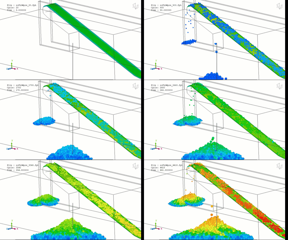
In the heavy industrial mining and bulk material handling sectors, the conveyor transfer chute is the foundational structural bridge guiding thousands of tons of material across transport lines. Its core engineering objective is to direct crushed ore, run-of-mine coal, or abrasive rock from an upstream discharge pulley down to a receiving conveyor belt safely and continuously.
Operating a transfer chute efficiently requires maximizing material throughput velocity, centralizing the loading profile to prevent belt tracking misalignment, and suppressing fugitive dust emissions. Because field modifications require plant shutdown windows costing millions of dollars in lost throughput, engineering teams deploy the Discrete Element Method (DEM) to model explicit particle-to-particle interactions and optimize internal hood-and-spoon geometries.
However, simulating a mining transfer chute via DEM is an exceptionally deceptive, highly non-linear mechanical challenge. Bulk material does not travel through a chute as an isolated stream of smooth, unbreakable spheres. It travels as a highly dense, interlocking mass of irregular geometries that compress, fracture, and wedge against each other. If your simulation setup relies on default, uncalibrated contact models or ignores particle breakage, your solver will completely miss localized structural blockages—leaving your design team blind to efficiency-killing material plugging and premature liner wear.
1. The Physics Anchor: Contact Mechanics and Particle Interaction Topologies
The granular dynamics inside a mining transfer chute are governed by Newton’s laws of motion tracked across millions of individual solid bodies. Unlike fluid simulations, the primary mechanism dictating material velocity and structural wear is the non-linear force transmission occurring during high-speed particle collisions.
To capture this mathematically, simulations must resolve normal and tangential force components at every individual contact point using advanced contact models, such as the Hertz-Mindlin or Linear Spring-Dashpot frameworks. The structural environment breaks into highly distinct, competing interaction topologies:
[Ore Stream Discharges From Belt] ➔ [Enters Chute Under High Normal Force] ➔ [Particles Interlock and Compress] ➔ [Localized Shear Strain Spikes] ➔ [Energy Dissipates via Plastic Deformation] ➔ [Material Stalls or Plugs]
- Normal Force Dissipation: When a dense column of material strikes an internal deflector plate, the kinetic energy is absorbed through micro-deformation at the particle contacts. The normal force is governed by the material’s Young’s Modulus and Poisson’s Ratio.
- Tangential Friction Resistance: As particles slide against each other or the steel liner, they experience tangential forces governed by the coefficients of static friction and rolling friction. Rolling friction acts as a mathematical torque that resists rotation, mimicking the mechanical interlocking of real-world angular rocks.
- The Smeared Fracture Trap: If the ore is brittle or contains natural internal fault lines, high-impact forces will shatter the material. If your DEM setup treats particles as unbreakable elements, it ignores this particle breakage. In reality, when rocks shatter into smaller fragments, the void fraction of the material bed collapses, drastically increasing the bulk density and shifting the internal friction angle, which can lock the material into an unmovable plugging mass.
2. Industry Context: Where Contact Precision Safeguards Mining Capital
Optimizing transfer chute internal profiles and maximizing material throughput through high-fidelity DEM directly dictates the infrastructure longevity, operational safety, and hourly production margins of major mining assets:
- Hard-Rock Iron Ore and Copper Processing: Processing high-tonnage abrasives causes rapid degradation of structural steel. Engineers use DEM to design specialized rock boxes—internal ledges that intentionally trap a dead-bed cushion of ore, forcing incoming rocks to strike other rocks rather than the bare metal structure, extending the chute’s working life from months to years.
- Receiving Belt Soft-Loading and Centralization: Off-center loading occurs when material exits a chute striking one side of the receiving belt, causing immediate belt misalignment, structural edge damage, and material spillage. DEM allows designers to contour the curved exit “spoon,” ensuring the ore stream lands dead-center on the receiving belt while matching the belt’s forward linear velocity to eliminate friction burn.
- Managing Cohesive and Sticky Materials: When mining in high-moisture or clay-heavy regions, material can become highly cohesive. Particles stick to the chute walls and to each other, building a thick layer of material that restricts the flow path. Engineers deploy advanced cohesion models (such as the JKR or SUIDS models) to determine the exact tilt angle required to keep the sticky material moving without plugging.
3. The Traps & Friction: Why Conveyor Chute DEM Fails
Predicting the exact material flow path, wear profiles, and localized jamming zones inside a heavy industrial chute requires avoiding common simulation shortcuts. Defaulting to standard configurations leads to three severe traps:
Relying on Manufacturer-Default Material Parameters
The most common and destructive pitfall in chute DEM projects is inputting standard textbook or software-default values for material properties like the coefficient of restitution or static friction. Granular materials are highly chaotic and context-dependent. A slight 5% variance in moisture content or surface roughness can double the material’s bulk internal friction angle. If your simulation parameters are not explicitly calibrated using physical lab benchmarks—such as angle of repose or draw-down tests—the solver will show smooth material flow on your screen while your real-world chute suffers from immediate plugging.
Utilizing Simplified Spherical Multi-Sphere Formulations Blindly
To dodge the massive computational cost of calculating contacts on complex shapes, engineers frequently model crushed rocks as perfect spheres or simple, coarse multi-sphere clumps. While this approach saves processing time, it introduces a severe geometric bias. Perfect spheres roll much faster and pack tighter than real, angular rocks. By over-simplifying the particle topology, the simulation severely under-predicts the localized shear strength of the moving material bed, leaving your design team blind to high-stress interlocking thresholds that cause structural bridging.
Ignoring the Mechanical Feedback: High Shear Wear
DEM software calculates wall wear using energetic models like Archard’s Wear Law, which relates volume mass loss to normal contact force and sliding distance. A common mistake is analyzing wear under static, steady-state throughput assumptions. In a real chute, the impact zone experiences transient, cyclic surges as material discharges from the belt. If your DEM run is too short to capture these fluctuating loading cycles, the solver will artificially smooth the wear profile, failing to alert you to highly localized impact hot spots that can wear through a chromium-carbide liner plate in a fraction of its predicted lifecycle.
4. Conquering the Granular Material Interface
A beautiful animation of rocks rolling through a digital chute is completely useless if your digital mass flow rates and liner lifespans do not correlate with physical facility logs. Validating your conveyor chute DEM pipeline requires moving past unverified default properties and deploying rigorously calibrated bulk material workflows. Your simulation parameters must be cross-referenced against empirical laboratory metrics—such as split-vessel shear tests, swing-arm impact test data, and laser-scanned wear telemetry from physical field liners—ensuring your coefficients of friction, particle breakages, and contact damping coefficients perfectly reflect physical factory boundaries.
Balancing transient multi-body contacts, angular shape resolutions, and non-linear cohesive forces demands an elite technical workflow. If your engineering design team is facing unexpected material plugging at transfer points, dealing with rapid degradation of expensive wear liners, or struggling to maintain center-loading profiles on receiving belts, bringing in a highly targeted technical extension can bridge the operational gap.
Author: Caesar Wiratama
Find me on Linkedin