
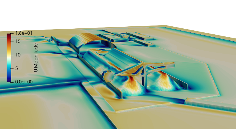
In large-scale open-pit coal mining and stockyard operations, fugitive coal dust emissions present a severe environmental, operational, and regulatory challenge. High-velocity ambient winds blowing across open stockpiles generate intense aerodynamic shear stress on the coal surface. Once the wind speed crosses a critical threshold, it lifts and entrains fine coal particles, creating massive, uncontained dust plumes that threaten local air quality [1, 2] and lead to significant material inventory loss.
To suppress these emissions, mining logistics and environmental engineering teams deploy windbreak walls and wind deflector panels along the perimeter of the stockyard. By introducing a structural barrier to intercept the incoming wind, the system aims to dramatically lower the wind velocity over the coal piles, keeping it safely below the threshold friction velocity required for dust lift-off.
Operating a wind deflector system efficiently requires balancing aerodynamic shelter distance, structural pressure drops, and wind-load mechanical stress. Because these massive industrial barriers are exposed to highly volatile, unpredictable atmospheric boundary layers, engineering teams rely heavily on Computational Fluid Dynamics (CFD) to optimize panel porosity profiles, determine optimal inclination angles, and calculate structural foundation loads.
However, simulating a coal mining wind deflector is an exceptionally deceptive bluff-body aerodynamic challenge. Atmospheric wind is not a clean, uniform stream; it is a highly turbulent, fluctuating fluid matrix. If your simulation framework relies on simplified macro-scale approximations or flattens these rapid transient flows into a steady-state formulation, your solver will completely miss localized structural stresses—leaving your design team blind to efficiency-killing transient eddy shocks.
1. The Physics Anchor: Porosity Friction and Bluff-Body Vortex Shedding
The fluid dynamics of a coal mining wind deflector are governed by the Navier-Stokes equations tightly coupled with an Atmospheric Boundary Layer (ABL) turbulence model. The fluid path transitions rapidly across two distinct computational zones: the porous panel interface and the downstream wake.
The primary physical mechanism dictating deflector performance is the balance between momentum destruction and vortex suppression:
[Incoming ABL Wind] ➔ [Hits Porous Deflector Panel] ➔ [Localized Porous Pressure Drop (Delta P)] ➔ [Fluid Core Splits: Displaced Top Stream & Controlled Leeward Leakage] ➔ [Suppression of Low-Pressure Wake Eddies]
- The Porous Pressure Drop: Unlike a solid wall, which forces wind to accelerate violently over the top edge and create a massive, low-pressure suction zone behind it, an optimized wind deflector utilizes specific structural porosity (typically between 30% to 50%). The aerodynamic drag across this porous sheet is modeled using viscous and inertial resistance coefficients.
- The Shear Layer Discontinuity: As wind passes through the deflector holes, it creates thousands of micro-jets that merge downstream, forming a controlled leeward leakage flow. This fluid stream actively fills the low-pressure void behind the wall, preventing the main stream passing over the top from curling downward into a violent, dust-lifting recirculation vortex.
- The Atmospheric Shear Profile: The incoming wind velocity increases non-linearly with height following a logarithmic or power-law ABL profile. This means the upper sections of the deflector experience significantly higher momentum and structural loading than the base.
2. Industry Context: Where Airflow Suppression Protects Local Communities
Optimizing wind deflector panel geometries and minimizing stockyard velocity fields through high-fidelity CFD directly dictates the environmental compliance, community safety, and operational margins of heavy mining assets:
- Open-Pit Stockyard Dust Suppression: Coal terminals manage massive stockpiles that sit exposed to coastal or regional high winds. Engineers use CFD to optimize the height and placement of perimeter windbreaks, striving to achieve a velocity reduction of over 50% across the entire footprint of the storage yard to suppress particle saltation.
- Haul Road and Material Transfer Stations: In open-pit operations, heavy mining trucks dump coal onto conveyor hoppers, creating localized, explosive dust bursts. Designers deploy targeted deflector hoods to channel incoming wind currents around the transfer zone, containing the particulate matter within the spray-misting boundaries.
- Preventing Structural Windbreak Overload: Windbreak walls span hundreds of meters in length and tens of meters in height, making them massive structural sails. During extreme weather events or sudden wind storms, these panels experience immense mechanical forces. Engineers use fluid-structure interaction (FSI) to ensure the foundations can withstand transient peak wind loads without structural failure.
3. The Traps & Friction: Why Mining Windbreak CFD Fails
Predicting the exact velocity field and shelter distance across a sprawling industrial stockyard requires navigating strict numerical and modeling traps:
Relying Solely on Steady-State RANS Solvers
To minimize processing times across large stockyard models, engineers frequently simulate windbreaks using steady-state Reynolds-Averaged Navier-Stokes (RANS) equations paired with standard k-epsilon or k-omega SST turbulence models. While this setup can roughly identify the average velocity reduction zone, it is fundamentally incapable of capturing the transient physics of atmospheric gusting. RANS artificially flattens the flow, “smearing” transient wind gusts into a continuous, static breeze. In reality, ambient wind hits the deflector in a series of violent, time-dependent packets. By smoothing over these dynamic velocity fluctuations, a steady-state formulation severely under-predicts the peak structural stresses (eddy shocks) acting on the panels and structural supports.
Utilizing Simplified Porous Media Models for Detailed Slatted Panels
To dodge the computational cost of meshing thousands of individual punched holes or slatted geometries, a common pitfall is modeling the deflector wall as a smooth, uniform Porous Medium block. While this approach can match global pressure drop values if calibrated perfectly, it completely flattens the local geometry. A simplified porous media model fails to resolve the distinct micro-jets and trailing shear layers that shed off the sharp metal edges of real slatted panels. This numerical smoothing under-predicts the localized turbulence kinetic energy right behind the wall, leading to simulations that miscalculate the exact inception point of the downstream recovery zone.
Neglecting Stockyard Topography and Pile Geometry Feedback
A coal stockpile is not a static, flat plane. It is a collection of dynamic, changing cones and ridges that continuously expand and contract as material is mined, stacked, and reclaimed. A common mistake in wind deflector CFD is simulating the boundary wall in isolation or using a simplified flat-ground model. In reality, the coal piles themselves act as massive bluff bodies that distort the local wind profiles. When wind passes over a deflector and encounters a tall coal pile downstream, the pile forces the air to compress and accelerate over its crest, creating localized high-velocity channels that trigger unexpected dust erosion despite the presence of the boundary wall.
4. Conquering the Atmospheric Boundary Boundary
A stunning color velocity contour plot of an industrial stockyard layout is completely useless if your digital velocity reduction metrics do not correlate with physical field data. Validating your wind deflector design CFD pipeline requires moving past idealized steady-state shortcuts and deploying transient, scale-resolving atmospheric fluid workflows, such as Large Eddy Simulation (LES) or Detached Eddy Simulation (DES). These digital models must be cross-referenced against empirical field metrics—such as real-time ultrasonic anemometer arrays mounted across active stockyards and wind-tunnel pressure tap maps validated on scaled physical models—ensuring your boundary layer profiles, panel porosity resistances, and transient gust loads perfectly reflect physical field conditions.
Balancing transient atmospheric boundary layers, non-uniform panel porosity structures, and dynamic multi-body stockpile geometry demands an elite technical workflow. If your engineering team is facing unexpected environmental compliance penalties due to dust blowouts, dealing with structural panel vibrations during wind storms, or struggling to determine the absolute minimum windbreak height required to clear regional EPA mandates, bringing in a highly targeted technical extension can bridge the operational gap.
Author: Caesar Wiratama
Find me on Linkedin