
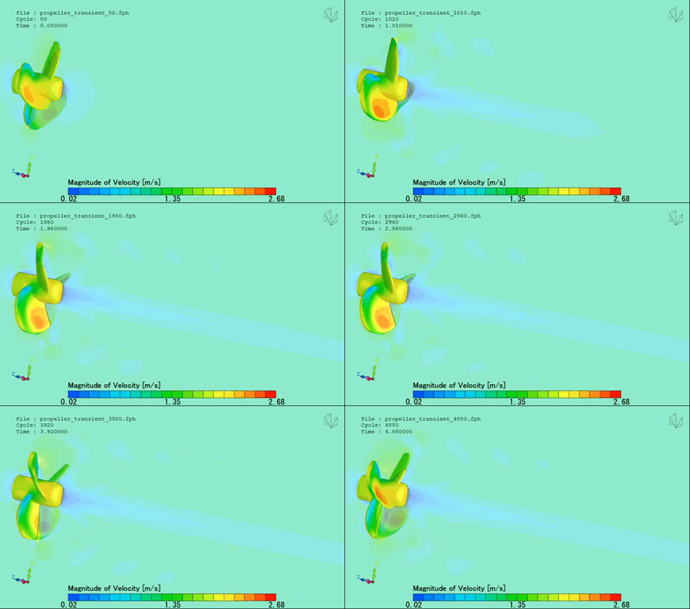
The marine propeller is the defining mechanical link responsible for translating a ship’s engine power into physical forward thrust. By rotating a series of twisted aerodynamic blades through the water, the propeller creates a pressure differential—low pressure on the suction side, high pressure on the pressure side—to push the vessel forward.
However, a marine propeller operates in a highly challenging hydrodynamic environment. It spins inside a heavily non-uniform wake field generated by the upstream ship hull.
Operating a marine propulsion system efficiently requires maximizing propeller open-water efficiency (eta_0) while strictly managing acoustic signatures and cavitation thresholds. Because physical cavitation tunnel tests are immensely expensive and prone to scale-model discrepancies, naval architects and propulsion manufacturers rely heavily on Computational Fluid Dynamics (CFD) to shape blade sections, optimize skew angles, and evaluate tip-clearance dynamics.
However, simulating a marine propeller is an exceptionally deceptive, highly multi-scale multi-phase challenge. If your simulation framework relies on simplified steady-state approximations or flattens the rotational wake into coarse grids, your solver will suffer from smeared tip vortices and remain blind to destructive phase changes—leaving your design team with highly inaccurate efficiency predictions.
1. The Physics Anchor: Asymmetric Inflow and the Rayleigh-Plesset Bubble Interface
The multi-phase fluid dynamics of a marine propeller are governed by the Navier-Stokes equations tightly coupled with a Multiphase Cavitation Model (such as the Schnerr-Sauer or Zwart-Gerber-Belamri formulations) operating under a non-uniform inflow. The fluid behavior transitions rapidly across complex physical states:
[Hull Blocks Airflow] ➔ [Asymmetric Wake Field Inflow Enters Propeller Disk] ➔ [Blade Experience Cyclic Angle of Attack Shifts] ➔ [Suction Pressure Drops Below Vapor Pressure] ➔ [Transient Sheet Cavitation Inception]
- The Asymmetric Wake Interface: A propeller does not encounter a perfectly uniform stream of water. The presence of the upstream hull and stern tube creates a highly non-uniform wake field. As a blade rotates through a single 360-degree cycle, it continuously encounters varying inflow velocities, forcing the blade sections to experience violent, cyclic shifts in their effective angle of attack.
- The Rayleigh-Plesset Cavitation Boundary: On the suction side of the blade, these rapid angle-of-attack spikes cause the local static pressure to drop abruptly. If the pressure falls below the liquid’s water vapor pressure, the liquid tears apart, flashing instantly into transient vapor cavities. The expansion and eventual violent collapse of these bubbles are governed by the Rayleigh-Plesset equation.
- The Tip Vortex Discontinuity: High-pressure fluid leaks across the blade tip to the low-pressure side, coiling into a highly dense, high-velocity tip vortex. The core of this vortex experiences an extreme pressure drop, making it the primary inception site for tip vortex cavitation, which radiates high-frequency acoustic noise and damages downstream rudders.
2. Industry Context: Where Propulsion Integrity Secures Fleet Efficiency
Optimizing blade geometries and suppressing transient cavitation loops through high-fidelity CFD directly dictates the operational windows, fuel economics, and structural lifecycles of modern maritime fleets:
- Commercial EEDI Compliance and Fuel Savings: Tightening international Energy Efficiency Design Index (EEDI) regulations force shipping lines to optimize propulsion efficiency. Engineers use CFD to design advanced Propeller Boss Cap Fins (PBCF) or energy-saving ducts that diffuse the hub vortex, recovering lost rotational energy to unlock 3–5% fuel savings.
- Naval Acoustic Discretion and Stealth: For military vessels and submarines, avoiding cavitation is a critical survivability metric. Cavitation bubble implosions emit unique acoustic signatures that can be detected by sonar miles away. Designers deploy transient, scale-resolving CFD to map the exact Cavitation Inception Speed (CIS), shaping blade skew to delay bubble formation.
- Preventing Blade Erosion and Material Fatigue: When sheet cavitation bubbles collapse violently against a blade surface, they generate localized microscopic fluid jets that hit the metal at supersonic speeds, producing impact pressures up to 10,000 atmospheres. Over months of operation, this mechanical hammering pits and destroys bronze propellers. CFD allows engineers to relocate vapor collapse zones safely off the trailing edge.
3. The Traps & Friction: Why Propeller CFD Fails
Predicting the exact efficiency and cavitation limits of a high-speed rotating blade requires navigating strict numerical and boundary traps:
Relying Blindly on the Moving Reference Frame (MRF) Shortcut
To minimize processing times, a common engineering pitfall is simulating propellers using the steady-state Moving Reference Frame (MRF) or Mixing Plane techniques. These methods apply a static rotational force field to the fluid zone, which is highly accurate for a propeller operating in a perfect, uniform stream. However, because a real marine propeller spins inside a heavily non-uniform hull wake, its flow is inherently transient. MRF completely flattens these cyclic variations, failing to predict the cyclic growth and collapse of transient sheet cavitation.
Misconfiguring the Grid Resolution in the Tip Vortex Path
A tip vortex is exceptionally sensitive to numerical damping. If your volume mesh cells grow larger or become highly skewed as they stretch downstream of the blade tip, the mathematical solver will introduce massive numerical diffusion. This error causes the computed vortex core to artificially smear, dissipate, and lose its low-pressure peak within a few centimeters of the blade. Without micro-scale cylindrical mesh refinement zones tracking the helical vortex path, your simulation will remain completely blind to tip vortex cavitation.
Ignoring Dissolved Gas Content and Nucleation Impurities
A common pitfall is treating the seawater as a pure, deaerated liquid. In real-world ocean environments, water contains micro-bubbles of dissolved non-condensable gases (like air) and microscopic organic impurities. These impurities act as nucleation sites that cause cavitation to occur at pressures significantly higher than the theoretical pure vapor threshold. If your multi-phase solver utilizes default, idealized parameters that ignore dissolved gas content and local surface tension variations, the simulation will severely under-predict the volume of vapor generated.
4. Conquering the Rotational Multi-Phase Interface
A stunning color velocity contour plot of an impeller blade is completely useless if your digital open-water thrust (KT) and torque (KQ) coefficients do not correlate with physical test matrix data. Validating your marine propeller CFD pipeline requires moving past steady-state shortcuts and deploying transient, sliding mesh or overset grid scale-resolving workflows, such as Detached Eddy Simulation (DES). These digital models must be cross-referenced against empirical laboratory metrics—such as high-speed video frames from depressurized cavitation tunnels and international ITTC propulsion benchmarks (e.g., the Potsdam Propeller Test Case)—ensuring your bubble dynamics, wake field interactions, and core pressure drops perfectly reflect physical ocean conditions.
Balancing transient rotating grids, multiphase phase-change equations, and high-resolution helical vortex tracking demands an elite technical workflow. If your engineering team is facing unexpected thrust degradation during field trials, dealing with severe vibration issues on the hull aft-deck, or struggling to match digital cavitation patterns with physical tunnel photos, bringing in a highly targeted technical extension can bridge the operational gap.
Author: Caesar Wiratama
Find me on Linkedin