
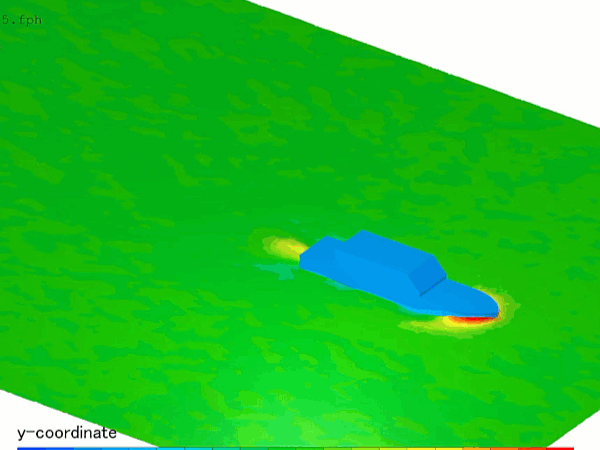
When a ship hull moves through the ocean, it must continuously push a massive volume of water out of its path. This aggressive displacement generates a distinct, V-shaped surface pattern trailing behind the vessel, universally known as the Kelvin wave wake. The mechanical energy required to continuously generate and maintain these surface waves translates directly into a massive physical barrier: wave-making drag (or wave resistance). At high cruising speeds, wave-making drag escalates exponentially, frequently accounting for over 60% of a ship’s total aerodynamic and hydrodynamic resistance.
To lower fuel consumption and optimize hull lines, naval architects and shipyards rely heavily on Computational Fluid Dynamics (CFD).
However, simulating wave-making drag is a deceptive multi-phase challenge. A moving ship does not travel through a rigid path; it actively generates its own transient wave field while experiencing dynamic shifts in vertical position and tilt. If your simulation setup relies on simplified, calm-water shortcuts or flattens the free-surface interface into coarse grids, your solver will suffer from severe numerical wave damping—leaving your design team blind to the vessel’s true wave drag penalty.
1. The Physics Anchor: Wave-Interference Mechanics and Dynamic Submergence
The multi-phase fluid dynamics of hull wave drag are governed by the Navier-Stokes equations tightly coupled with a Volume of Fluid (VOF) free-surface tracking method and rigid-body dynamics. The primary mechanism dictating wave-making drag is the non-linear interaction between two distinct wave systems generated by the hull:
[Vessel Accelerates Forward] ➔ [High Pressure at Bow Creates Bow Wave] ➔ [Low Pressure at Stern Creates Stern Wave] ➔ [Wave Systems Interfere Phase-Wise] ➔ [Dynamic Trim and Sinkage Adjustments] ➔ [Wave-Making Drag Spikes]
- The Bow and Stern Wave Discontinuities: As the hull slices forward, a localized high-pressure zone forms at the nose, pushing up a massive bow wave. Simultaneously, the fluid accelerating around the curved rear of the vessel creates a low-pressure zone, generating a secondary stern wave.
- The Interference Penalty: These two wave fields travel at the same velocity as the ship, creating an interference pattern along the hull. If the crest of the bow wave aligns with the crest of the stern wave, they reinforce each other, causing a massive spike in wave-making drag.
- Dynamic Trim and Sinkage Feedback: This asymmetric pressure distribution actively alters the ship’s physical position in real-time. The vessel naturally drops lower into the water (sinkage) and tilts backward (trim). This dynamic change in the wetted surface area modifies the hull shape encountered by the fluid, creating a direct feedback loop that continuously alters the drag profile.
2. Industry Context: Where Wave Disruption Secures Fleet Efficiency
Optimizing hull lines and suppressing wave-making resistance through high-fidelity CFD directly dictates the carbon footprint, operational costs, and global emissions compliance of modern maritime fleets:
- Bulbous Bow Optimization for Commercial Cargo: Mega-container ships feature a large, protruding bulb underneath the waterline at the bow. This bulb is custom-engineered using CFD to generate its own wave system that sits perfectly out of phase with the hull’s natural bow wave. The two waves destructively interfere and flatten each other out, unlocking up to a 15% reduction in total wave drag.
- Eco-Streaming for Slow-Cation Transit: When global shipping lines utilize “blank sailings” or slow-steaming to cut fuel burn, the ship operates far below its original design speed. Because wave drag scales non-linearly with speed, engineers use CFD to re-evaluate bow bulb configurations for lower velocities, ensuring the bulb doesn’t become a drag liability at lower Froude numbers.
- High-Speed Naval Catamarans and Trimarans: Multi-hull vessels split their displacement across long, slender side hulls. Designers deploy transient wave-drag simulations to optimize the physical spacing between the hulls, ensuring the wave wake from the center hull does not constructively slam into the side structures, which would choke the fluid channels and spike wave-making resistance.
3. The Traps & Friction: Why Wave Drag CFD Fails
Predicting the exact wave profile and pressure distribution along a moving hull requires navigating strict numerical and boundary traps:
Relying on Fixed-Hull, Steady-State RANS Shortcuts
The most common and costly pitfall in maritime resistance CFD is simulating a hull while keeping it locked in a perfectly fixed, static vertical position. While this shortcut can give a rough estimate of calm-water skin friction, it is entirely blind to dynamic trim and sinkage. If the solver is not configured with an active six-degrees-of-freedom (6-DoF) rigid-body motion model, it will completely miss the increased displacement caused by the ship squatting lower into the water at high speeds, under-predicting wave-making drag by up to 25%.
Misconfiguring VOF Grid Resolution in the Kelvin Wake Zone
To capture how waves propagate behind the hull and extract energy from the propulsion loop, the VOF interface must remain razor-sharp. If your volume mesh is too coarse downstream of the stern, the mathematical solver will introduce severe numerical diffusion. This error causes the computed wave crests to artificially decay and flatten out within a few meters of the ship—a phenomenon known as numerical wave damping. Without precise, flow-aligned isotropic grid refinement zones tracking the wave wake, your solver will output a false low-drag dataset because it cannot see the wave energy escaping.
Utilizing Standard Mesh Smoothing for Severe Squatting Regimes
When high-speed vessels or shallow-water barges accelerate, they experience intense squatting forces that rapidly displace the hull downward. If you default to standard spring-based mesh smoothing algorithms to handle this grid movement, the cells adjacent to the sharp transom stern or keel will quickly pinch into zero or negative volume elements, crashing the solver instantly. Overcoming this structural limitation requires abandoning basic mesh morphing in favor of advanced Overset Mesh (Chimera grids), allowing a high-resolution hull grid to slide and tilt cleanly over a static background ocean grid without any cell deformation.
4. Conquering the Wave-Making Interface
A stunning color animation of a ship throwing digital spray is completely useless if your computed drag curves do not correlate with empirical maritime benchmarks. Validating your wave-drag CFD pipeline requires moving past calm-water shortcuts and deploying fully resolved, transient 6-DoF multi-phase workflows. These digital models must be cross-referenced against empirical laboratory metrics—such as tow-force records and wave-profile data validated on standardized research hulls like the Wigley Hull or the Series 60 container ship in international towing tanks—ensuring your VOF surface tension settings, dynamic sinkage metrics, and wave-interference fields perfectly reflect physical ocean conditions.
Balancing transient free-surface VOF tracking, high-speed scale-resolving turbulence, and complex overset rigid-body grids demands an elite technical workflow. If your engineering team is facing unexpected solver divergence near peak operating speeds, dealing with unmanageable wave damping downstream, or struggling to match digital resistance curves with towing tank logs, bringing in a highly targeted technical extension can bridge the operational gap.
Author: Caesar Wiratama
Find me on Linkedin