
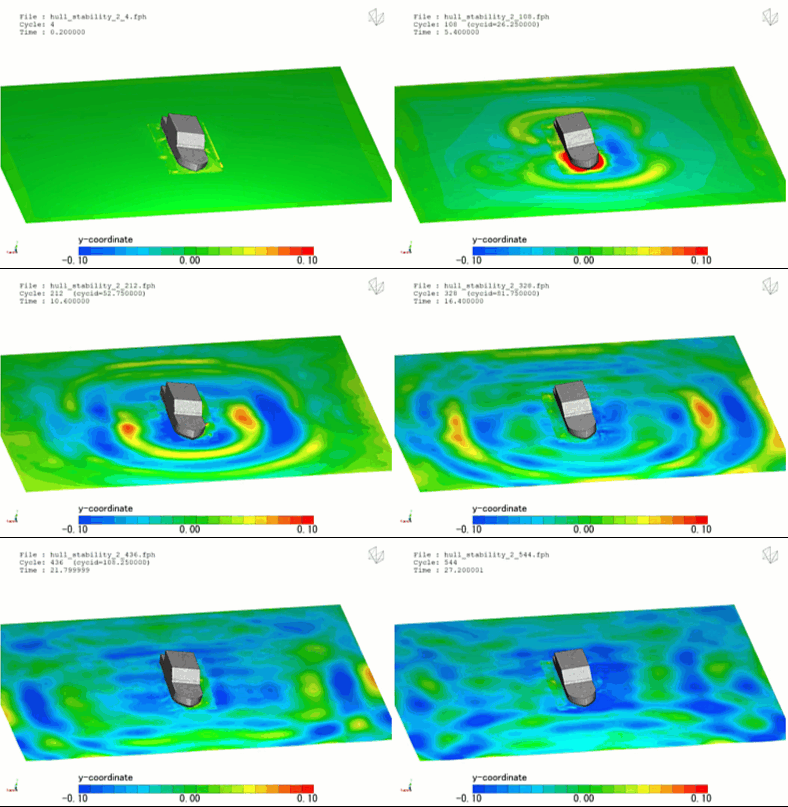
In naval architecture and marine engineering, performing a hull stability analysis is the definitive safety checkpoint that dictates a vessel’s seaworthiness. Whether designing an ultra-large container carrier, an offshore crew transfer vessel, or a massive floating production storage and offloading (FPSO) unit, the core engineering goal is identical: to guarantee the vessel possesses sufficient restoring forces to right itself after being deflected by external wind, wave, or operational loading.
Operating a marine asset safely requires mapping out precise margins for both intact and damaged stability. Because a vessel must survive extreme, non-linear environmental states, engineering teams can no longer rely solely on classic static formulas. Modern design validation requires deploying high-fidelity Computational Fluid Dynamics (CFD) to map dynamic capsizing thresholds and assess real-world maritime safety boundaries.
However, simulating a hull stability event is an exceptionally deceptive, highly non-linear multi-physics challenge. A tilting ship hull does not operate in a vacuum; it forces a massive, high-momentum exchange between fluid displacement and rigid-body mechanics. If your simulation setup relies on simplified hydrostatic assumptions or flattens transient ocean waves into uniform static grids, your solver will completely miss dangerous resonant behaviors—leaving your design team blind to efficiency-killing dynamic wave sloshing.
1. The Physics Anchor: Metacentric Shifting and Dynamic Metacentric Traps
The fluid dynamics inside a hull stability analysis are governed by the Navier-Stokes and rigid-body dynamic equations tightly coupled with a Volume of Fluid (VOF) free-surface tracking method. The simulation must track the relationship between the vessel’s Center of Gravity (G) and its shifting Center of Buoyancy (B):
[External Wave Heels Hull] ➔ [Wetted Hull Geometry Shifts Asymmetrically] ➔ [Center of Buoyancy Migrates Outward] ➔ [Metacentric Height (GM) Metamorphoses Transiently] ➔ [Dynamic Righting Arm (GZ) Fluctuations]
- The Moving Center of Buoyancy: When a ship heels over, the underwater shape of the hull changes asymmetrically. The Center of Buoyancy—the geometric center of the displaced water volume—migrates outward toward the low side of the vessel, establishing a righting arm (GZ) that generates a restoring moment.
- The Metacentric Height (GM) Trap: Traditional analysis calculates stability using a static metacentric height assumption. In physical seas, however, as ocean waves pass along the hull, the local water level rises and falls dynamically. This continuous fluid displacement causes the metacentric height to metamorphose transiently in real-time. If the wave frequency couples with the vessel’s natural roll frequency, the restoring arm can momentarily drop to zero, triggering parametric rolling and sudden, catastrophic capsizing.
2. Industry Context: Where Dynamic Righting Moments Secure Ocean Assets
Optimizing hull topologies and predicting dynamic stability envelopes through high-fidelity CFD directly dictates the operational windows, safety certifications, and structural survivability of modern maritime assets:
- Commercial Container Carrier Parametric Rolling: Mega-ships with massive bow flares are highly susceptible to parametric rolling in head seas. When a wave crest passes the midship, the water level at the bow and stern drops, causing a sudden loss of stability that can roll a vessel past 30 degrees in a few cycles. Engineers use CFD stability models to optimize hull lines, ensuring the vessel maintains a safe, stable righting arm across varying wave encounters.
- Offshore Wind Installation Vessels: Jack-up and heavy-lift crane vessels experience immense shifting loads when lifting multi-ton wind turbine components. Designers deploy detailed 6-DoF (Six Degrees of Freedom) simulations to analyze transient stability during crane maneuvers, preventing localized structural tipping if a wave strikes mid-lift.
- Damaged Stability and Enclosed Compartment Flooding: When a hull is breached, water floods internal compartments, creating a highly dangerous free-surface effect where fluid sloshes across the deck. Engineers use multi-phase CFD to simulate how this internal sloshing couples with external wave forces, determining if the onboard bilge pump arrays can stabilize the vessel before it founders.
3. The Traps & Friction: Why Hull Stability CFD Fails
Predicting the exact moment a ship loses its righting lock requires avoiding common numerical and boundary shortcuts. Defaulting to standard industrial setups leads to three severe traps:
Relying Solely on Quasi-Static Hydrostatic Software Charts
The most common and dangerous pitfall in stability analysis is relying exclusively on traditional, quasi-static hydrostatic software routines. These legacy tools evaluate stability by tilting the hull mathematically in perfectly calm water, completely ignoring fluid momentum, wave actions, and forward speed. In reality, the dynamic wave profile generated by a moving hull severely alters the local buoyancy distribution. By ignoring these transient aerodynamics, a static calculation smooths over the safety margins, leaving your asset management team completely blind to dynamic capsizing thresholds.
Misconfiguring the VOF Free-Surface Grid in the Splash-Zone
To capture how ocean waves strike and lift a tilting hull, the VOF interface must remain razor-sharp. If your volume mesh is too coarse in the splash-zone—the regional belt where air and water continuously smash against the hull side—the mathematical solver will suffer from severe numerical diffusion. This error introduces artificial fluid damping, smoothing out the true force of the wave strike. Without precise, flow-aligned isotropic grid refinement zones tracking the water level, your simulation will under-predict the maximum heeling moment experienced by the vessel.
Utilizing Standard Mesh Deformation for Large-Angle Rolling
When simulating extreme stability events, such as a dead-ship capsize test in a storm, the hull undergoes massive, large-amplitude angular rotations. If you default to standard spring-based mesh smoothing algorithms, the cells adjacent to the bilge keels or deck edges will quickly squeeze into zero or negative volume elements, crashing the solver instantly. Overcoming this structural limitation requires deploying advanced Overset Mesh (Chimera grids), allowing a high-resolution hull grid to rotate freely past 90 degrees over a static, background ocean grid without any cell deformation.
4. Conquering the Dynamic Seakeeping Boundary
A stunning color animation of a hull rolling through digital waves is completely useless if your computed righting arms and response amplitude operators (RAOs) do not correlate with physical maritime benchmarks. Validating your hull stability CFD pipeline requires moving past static charts and deploying fully resolved, transient 6-DoF multi-phase workflows. These digital models must be cross-referenced against empirical laboratory metrics—such as physical towing tank scale-model tests and international ITTC (International Towing Tank Conference) stability benchmarks—ensuring your VOF surface tension settings, dynamic trim metrics, and rigid-body mass moments perfectly reflect physical ocean conditions.
Balancing transient free-surface VOF tracking, high-speed scale-resolving turbulence models, and complex overset rigid-body grids demands an elite technical workflow. If your engineering team is facing unexpected solver divergence near capsizing thresholds, dealing with unmanageable roll accelerations in heavy states, or struggling to couple internal compartment sloshing with external sea forces, bringing in a highly targeted technical extension can bridge the operational gap.
Author: Caesar Wiratama
Find me on Linkedin