
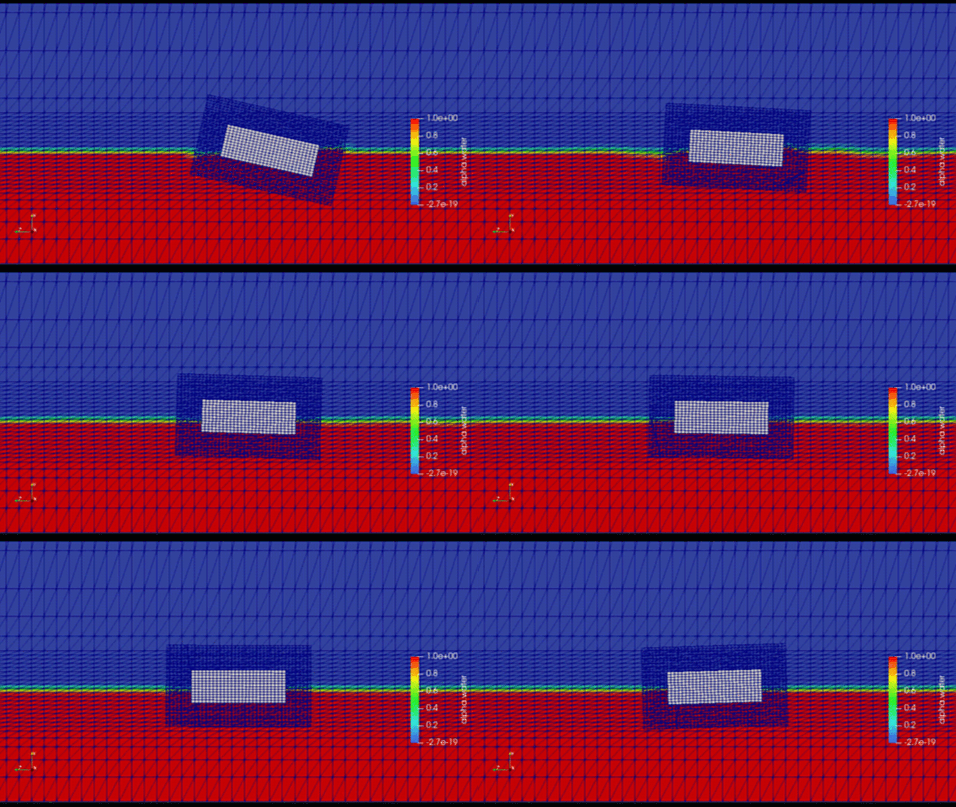
In naval architecture and offshore engineering, predicting how a hull or floating platform interacts with the ocean is the definitive baseline for vessel safety, structural integrity, and hydrodynamic efficiency. Whether designing an ultra-large container ship navigating heavy beam seas, a floating offshore wind turbine (FOWT) platform subjected to cyclic wave loading, or an autonomous underwater vehicle (AUV) breaking the surface interface, the core engineering goal is identical: to accurately map the dynamic six-degrees-of-freedom (6-DoF) structural motion coupled with complex fluid forces.
Operating a marine asset efficiently requires minimizing wave-making resistance, maximizing seakeeping comfort, and preventing structural capsizing under extreme environmental states. Because physical towing tank tests are immensely expensive and constrained by scale limitations, maritime engineers rely heavily on Computational Fluid Dynamics (CFD) to evaluate ship motions, predict green water bow slam events, and calculate mooring line tensions.
However, simulating a floating body is an exceptionally deceptive, highly non-linear multi-physics challenge. A marine vessel operates at the violent, shifting interface of two fluids with wildly different densities: air and water. If your simulation setup flattens these rapid transient interactions into a steady-state formulation or utilizes simplified mesh definitions, your solver will suffer from smeared free surfaces and artificial numerical submergence, outputting completely unphysical seakeeping data.
1. The Physics Anchor: Volume of Fluid Tracking and 6-DoF Mesh Morphing
The multi-phase fluid dynamics of a floating maritime body are governed by the Navier-Stokes equations tightly coupled with a Volume of Fluid (VOF) free-surface tracking method and rigid-body dynamic equations. The simulation must resolve fluid forces across an actively moving and morphing geometric boundary:
[Vessel Encounters Ocean Wave] ➔ [VOF Model Tracks Fluid Interface Density] ➔ [Pressure & Shear Forces Integrated Across Hull] ➔ [6-DoF Solver Calculates Force Matrix] ➔ [Mesh Formulations (Overset/AUM) Displace Grid]
- The VOF Multi-Phase Interface: To capture real-world ocean waves, the solver uses the VOF method to track the volume fraction of water and air in every individual cell. The interface must remain razor-sharp to correctly calculate the hydrostatic and hydrodynamic buoyancy forces acting on the hull.
- The 6-DoF Force Integration: Every time step, the fluid pressure and skin-friction shear forces are integrated across the entire wetted surface of the vessel. The resulting force and moment matrix is passed to a rigid-body solver that calculates the vessel’s linear (heave, surge, sway) and angular (roll, pitch, yaw) accelerations.
- The Mesh Displacement Challenge: Once the new physical position of the hull is calculated, the underlying computational grid must move to match it. If the mesh stretches or compresses excessively, cell skewness will spike, causing immediate solver divergence or unphysical pressure spikes.
2. Industry Context: Where Dynamic Stability Mapping Protects Megastructures
Optimizing hull topologies and predicting transient offshore motion profiles through high-fidelity CFD directly dictates the operational windows, fuel economics, and structural survivability of modern maritime assets:
- Commercial Container Ship Seakeeping: Modern mega-ships feature massive forward flares. When slamming into head seas, this flare creates a violent green water slam event where tons of ocean water crash onto the cargo deck. Engineers use transient CFD to map these impact pressures, strengthening structural bulkheads to prevent catastrophic structural buckling.
- Floating Offshore Wind Turbines (FOWT): FOWT platforms support immense aerodynamic towers operating in deep waters. Designers deploy coupled aerodynamic-hydrodynamic simulations to ensure that the combined forces of wind thrust on the blades and wave pitching on the floating pontoon do not trigger catastrophic resonance or structural capsizing.
- Subsea Oil & Gas Floating Production (FPSO) Vessels: FPSO vessels remain moored at a single ocean coordinate for decades. Engineers use long-duration transient simulations to map green water overtopping and vortex-induced motions (VIM), optimizing the layout of internal ballast tanks and mooring line fairleads to minimize hull fatigue.
3. The Traps & Friction: Why Maritime Floating Body CFD Fails
Predicting the true seakeeping and wave-resistance characteristics of a moving hull requires navigating strict numerical and boundary traps:
Relying Solely on Steady-State RANS and Fixed-Hull Shortcuts
To minimize computational run times, a common engineering pitfall is simulating ship hulls using steady-state Reynolds-Averaged Navier-Stokes (RANS) equations while keeping the hull locked in a fixed vertical position. While this shortcut can give a rough estimate of calm-water skin friction, it completely ignores dynamic trim and sinkage. As a ship gains forward speed, the pressure field under the hull drops, causing the vessel to naturally sink lower into the water and tilt backward. A fixed-hull model is entirely blind to this, severely under-predicting wave-making resistance.
Misconfiguring VOF Grid Resolution in the Wave-Zone
Ocean waves propagate across kilometers of space before hitting a vessel. If your volume mesh is too coarse near the air-water interface, or if your time steps are too large, the mathematical solver will introduce severe numerical diffusion. This error causes the waves to artificially decay and flatten out before they ever reach the ship—a phenomenon known as numerical wave damping. Without precise isotropic grid refinement zones tracking the free surface paired with high-order bounded VOF schemes, your simulation will evaluate the ship in calm water despite your wave generator settings.
Utilizing Standard Mesh Smoothing for Large Rolling Motions
When an offshore platform or ship experiences large-angle rolling motions (such as during a beam sea storm simulation), the grid cells adjacent to the hull are subjected to extreme deformation. If you default to standard spring-based mesh smoothing algorithms, the cells will quickly pinch into zero or negative volume elements, crashing the solver instantly. Overcoming this structural limitation requires abandoning basic mesh morphing in favor of advanced Overset Mesh (Chimera grids) or arbitrary Lagrangian-Eulerian (ALE) techniques, allowing a detailed hull grid to rotate freely over a static background ocean grid without any cell deformation.
4. Conquering the Deep-Ocean Multi-Phase Boundary
A stunning color animation of a hull splashing through digital waves is completely useless if your computed heave and pitch response amplitudes do not correlate with physical maritime benchmarks. Validating your floating body CFD pipeline requires moving past calm-water shortcuts and deploying fully resolved, transient 6-DoF multi-phase workflows. These digital models must be cross-referenced against empirical laboratory metrics—such as motion capture data and wave-profile records validated on standardized hulls like the KVLCC2 tanker or DTC container ship in international towing tanks—ensuring your VOF surface tension settings, wave generation profiles, and rigid-body configurations perfectly reflect physical ocean conditions.
Balancing transient free-surface tracking, high-fidelity scale-resolving turbulence models, and complex overset grid generation demands an elite technical workflow. If your engineering team is facing unexpected solver crashes during large-amplitude rolling tests, dealing with inaccurate wave-making drag predictions, or struggling to couple mooring line physics into your offshore models, bringing in a highly targeted technical extension can bridge the operational gap.
Author: Caesar Wiratama
Find me on Linkedin