
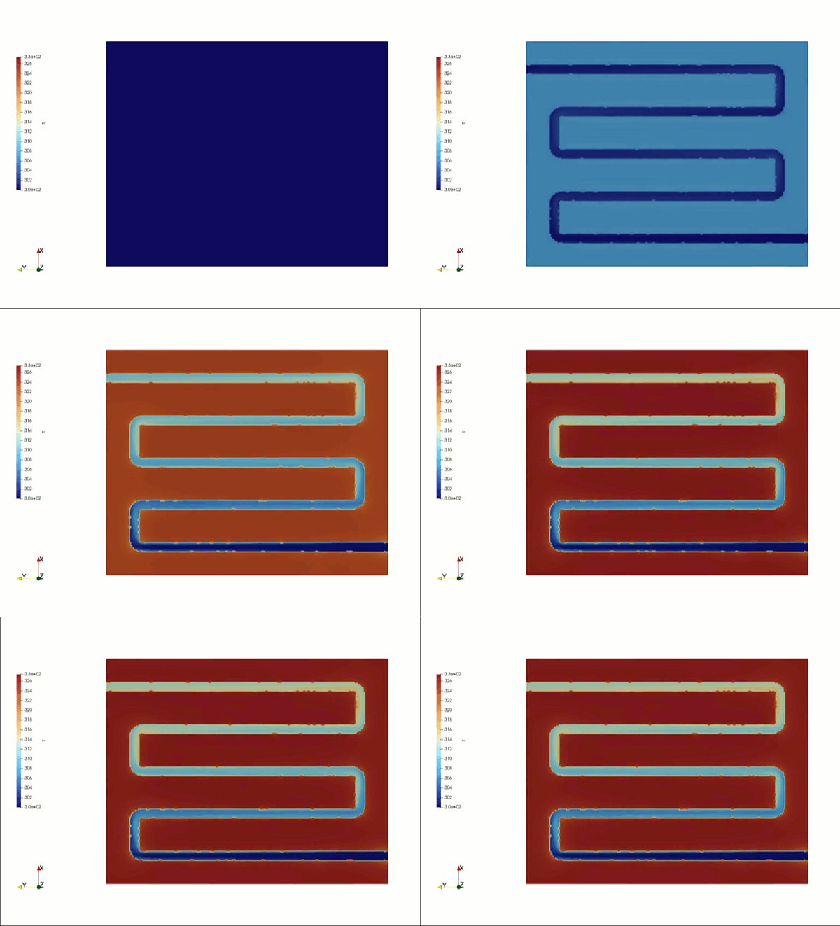
In high-power density electronics—spanning electric vehicle (EV) battery packs, server racks for artificial intelligence, and advanced aerospace avionics—the liquid cooling plate (or cold plate) is the definitive shield against thermal failure. By mounting a high-heat-flux electronic component directly onto a metal plate embedded with micro-channels, the system uses forced liquid convection to absorb and carry away extreme heat loads.
Operating a liquid cooling plate efficiently requires maximizing the overall heat transfer coefficient while strictly managing the mechanical pressure drop across the internal channels. Because modern computing chips and battery cells generate immense, localized heat spikes, engineering teams rely heavily on Computational Fluid Dynamics (CFD) to optimize pin-fin arrays, design internal channel paths, and evaluate alternative coolant flow rates.
However, simulating a liquid cooling plate is a deceptive multi-scale challenge. While fluid flow inside a single straight channel is highly predictable, the fluid trajectory across a massive array containing dozens of micro-channels is deeply non-uniform. If your simulation setup relies on idealized macro-scale thermal averages or flattens channel entry flow into coarse grid boundaries, your solver will completely miss localized flow imbalances—leaving your design team blind to efficiency-killing channel maldistribution.
1. The Physics Anchor: Manifold Pressure Gradients and Localized Thermal Choking
The thermal fluid dynamics inside a liquid cooling plate are governed by Conjugate Heat Transfer (CHT) equations, which model the simultaneous conduction of heat through the solid metal block and its subsequent convection into the moving liquid domain.
The primary physical mechanism dictating plate performance is channel-to-channel flow maldistribution. Unlike idealized textbook models that assume fluid splits perfectly and evenly among all available channels, real fluid manifolds experience dynamic pressure drops that distort the distribution pattern:
[Coolant Enters Inlet Port] ➔ [Passes Through Internal Manifold Header] ➔ [Dynamic Pressure Gradients Form Along Array] ➔ [First and Last Channels Starve or Over-flow] ➔ [Localized Thermal Choking Trap]
- The Manifold Pressure Gradient: As fluid enters the narrow inlet port, it travels into a distribution manifold that feeds the individual micro-channels. The fluid’s high forward momentum creates an immediate pressure gradient along this header. Channels positioned directly opposite the inlet often experience high velocity, while channels located at the furthest edges are heavily starved of fluid.
- The Thermal Choking Feedback Loop: In the starved micro-channels, the local fluid velocity plummets, dropping the localized heat transfer coefficient. Because the fluid moves sluggishly, it absorbs heat to its maximum capacity near the front of the plate and undergoes localized thermal choking. The fluid can no longer absorb additional heat, creating a massive, uncooled hotspot directly beneath the hottest part of the electronic component.
2. Industry Context: Where Uniform Chill Delivers Electronics Lifespan
Optimizing cold plate micro-channels and minimizing flow short-circuiting through high-fidelity CFD directly dictates the product reliability, warranty lifecycles, and performance limits of advanced electronics infrastructure:
- AI and Data Center Server Cooling: High-performance graphics processing units (GPUs) operate at extreme thermal loads. To prevent chips from throttling or failing prematurely, engineers use CFD to design micro-pin-fin arrays inside the cold plate, creating micro-vortices that disrupt the thermal boundary layer and maximize localized heat rejection.
- Electric Vehicle (EV) Extreme Fast Charging: During ultra-fast charging cycles, EV batteries generate immense internal heat. Cold plates running underneath or between modules must maintain a cell-to-cell temperature delta of less than 5 degrees Celsius. CFD allows battery designers to optimize serpentine fluid channels, preventing uneven cell degradation and mitigating the risk of thermal runaway.
- High-Power Radar and Avionics Systems: Military aircraft house dense radar transmit-receive modules operating in tight enclosures. Designers use multi-phase and transient CHT simulations to evaluate cold plate integrations, ensuring the system rejects heat uniformly even under high-G maneuvers that alter fluid sloshing profiles.
3. The Traps & Friction: Why Liquid Cold Plate CFD Fails
Predicting the true thermal efficiency and pressure recovery inside a dense micro-channel pack requires avoiding common numerical shortcuts. Defaulting to standard industrial setups leads to three severe traps:
Relying on Simplified Porous Medium Shortcuts for Large Channel Arrays
To minimize massive computational cell counts, engineers frequently model an entire micro-channel cooling plate by treating the internal channels as a uniform, smeared Porous Medium block. While this shortcut provides a rough approximation of the global pressure drop, it is entirely blind to individual channel maldistribution. A porous media model flattens the geometric transitions between the manifold header and the channel inlets. This blinding error causes the simulation to completely smooth over starved channels, outputting highly overly optimistic thermal effectiveness data.
Misconfiguring the Grid Resolution in Internal Pin-Fin Arrays
To boost heat transfer, modern plates embed hundreds of microscopic pin-fins or staggered ribs inside the fluid path. These features create tight, restrictive throat geometries where fluid velocity spikes and drops rapidly. If your volume mesh is too coarse around these pins, the mathematical solver will suffer from severe numerical diffusion, artificially smoothing out the local velocity peaks. Without micro-scale prism layer grid refinement paired with a robust turbulence model (such as the k-omega SST model), your simulation will completely miscalculate the localized pressure drop and heat transfer coefficient.
Ignoring Temperature-Dependent Viscosity Shifts in Glycol Coolants
When simulating liquid cooling plates handling glycol-water mixtures or dielectric fluids, a common pitfall is configuring the CFD solver with a constant fluid viscosity. In reality, these fluids exhibit extreme temperature-dependent viscosity shifts, especially during cold-weather startups. As the fluid absorbs heat along the plate, its viscosity drops dramatically, which reduces flow resistance and alters the velocity profile in real-time. Failing to couple the solver with a highly accurate non-linear viscosity model will cause the simulation to predict incorrect channel distribution profiles.
4. Conquering the Compact Thermal Boundary
A beautiful, colorful temperature contour plot of a cold plate profile is completely useless if your digital channel-split metrics do not correlate with physical test bench data. Validating your liquid cooling plate CFD pipeline requires moving past single-channel shortcuts and deploying fully resolved, transient CHT loops. These digital models must be cross-referenced against empirical laboratory metrics—such as real-time differential pressure transducer data across individual ports and infrared thermal camera logs validated on physical cold plate test fixtures—ensuring your fluid splits, pressure drops, and localized thermal resistances perfectly reflect physical field reality.
Balancing transient multi-scale conjugate heat transfer, non-uniform manifold pressure distributions, and micro-scale pin-fin tracking demands an elite technical workflow. If your engineering team is facing unexpected pressure drops across an electronics enclosure, dealing with localized GPU thermal throttling, or struggling to maintain uniform temperatures across an EV battery pack, bringing in a highly targeted technical extension can bridge the operational gap.
Author: Caesar Wiratama
Find me on Linkedin