
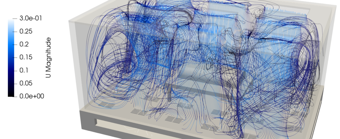
Cleanrooms are highly specialized, high-consequence infrastructure assets deployed across semiconductor fabrication, pharmaceutical manufacturing, and aerospace assembly sectors. These environments enforce stringent limits on airborne particulate counts, temperature fluctuations, and relative humidity to protect highly sensitive processes from contamination. Unlike standard commercial spaces, cleanroom HVAC systems must maintain absolute control over airflow directionality to rapidly sweep away contaminants generated by personnel or machinery. Computational Fluid Dynamics (CFD) provides contamination control and facility engineers with a precise digital microenvironment to track microscopic particulates, evaluate pressure cascading, and refine air distribution layouts with high fidelity.
Technical and Theoretical Description
From an aerodynamic and environmental standpoint, a cleanroom HVAC system operates on highly controlled, low-turbulence, often unidirectional (laminar) internal fluid dynamics governed by the three-dimensional Navier-Stokes and energy equations. Cleanrooms are classified under international standards like ISO 14644-1 based on the maximum allowable particle concentration per cubic meter of air. To achieve this, cleanroom designs heavily rely on massive banks of High-Efficiency Particulate Air (HEPA) or Ultra-Low Penetration Air (ULPA) filters positioned in the ceiling, which discharge air downward at a uniform velocity. CFD simulations utilize advanced turbulence models, most commonly the Reynolds-Averaged Navier-Stokes (RANS) Shear Stress Transport (k-omega SST) or Realizable k-epsilon formulations, to map flow fields and identify unwanted recirculation zones or dead spaces where particles can become trapped.
The core theoretical focus in cleanroom modeling centers on tracking contaminant transport and maintaining strict pressure cascading using a coupled multi-physics framework:
- Particulate Transport & Settling: Contaminants are treated as a discrete phase and simulated using Eulerian-Lagrangian tracking or passive scalar species transport. Individual particles are tracked by applying Newton’s second law, calculating the balance of hydrodynamic drag, gravity, and buoyancy forces to evaluate whether particulates will remain suspended, be drawn into floor-level return grilles, or settle onto critical processing surfaces.
- Air Change Rates and Age-of-Air: The simulation continuously calculates local Mean Age of Air (MAA), a theoretical metric defined by plain-text differential transport equations that quantifies the freshness of the air across the room and highlights stagnant zones prone to contamination buildup.
- Pressure Cascading: Cleanrooms utilize positive pressure differentials relative to surrounding corridors to prevent external unfiltered air from infiltrating the space. CFD solves the mass conservation equations across leakage paths and automated door openings to verify that the pressure gradient remains uncompromised during operational changes.
Business Value of CFD Implementation
From a commercial perspective, deploying CFD in cleanroom HVAC engineering yields massive capital expenditure (CapEx) savings and directly protects ultra-high-yield manufacturing processes. Constructing a state-of-the-art semiconductor fab or pharmaceutical cleanroom costs millions of dollars, with the HVAC network consuming up to 50% of the initial facility footprint. CFD serves as a rapid virtual prototyping environment, enabling design teams to test dozens of filter coverage ratios, raised-floor perforation patterns, and equipment layouts in software before freezing the hardware architecture. This ensures that the facility achieves its target ISO classification upon startup, avoiding catastrophic post-construction structural remediations.
In terms of operational expenditures (OpEx), a CFD-refined cleanroom design directly drives down energy consumption and operational risks. Cleanrooms historically rely on massive over-design factors, running at excessively high air change rates (often 200 to 600 air changes per hour) to guarantee cleanliness, which inflicts massive annual utility and carbon costs. CFD optimization allows engineers to safely downsize fan capacities and reduce airflow speeds in non-critical zones while maintaining absolute contamination control in the primary process areas. Furthermore, minimizing localized thermal hot spots near heat-generating production machinery prevents thermal expansion of microchip wafers or denaturing of biological products, directly maximizing manufacturing yields and accelerating return on investment.
Challenges of CFD in Cleanroom Modeling
Despite its analytical power, simulating cleanroom environments introduces steep multi-scale physical and numerical challenges. The foremost obstacle is the extreme geometric scale discrepancy combined with dense flow obstructions. A complete cleanroom bay can span dozens of meters, yet the simulation must simultaneously resolve millimeter-scale filter seals, localized perforation slots in the raised flooring, and complex automated robotic track systems. Fully meshing these intricate features explicitly creates an unmanageable cell count that strains high-performance computing resources.
Another major hurdle is characterizing the transient, dynamic nature of operational cleanrooms. Contamination profiles are rarely static; they are highly dependent on the movement of personnel, opening and closing of airlocks, and varying thermal loads from electronic processing tools. If a simulation simplifies these boundaries into static averages, it misses the transient vortex formations caused by a passing operator, which can pull contaminants from the floor back up onto a clean workbench. Furthermore, modeling the aerodynamic resistance of dust-loaded HEPA filters requires careful calibration of porous media models to prevent distorting downstream velocity profiles.
Solutions for High-Fidelity Simulation
To overcome these multi-scale and transient challenges, modern facility engineering workflows utilize specialized numerical sub-models and highly structured meshing strategies. Engineers resolve the extreme geometric scale discrepancies by representing HEPA and ULPA filter banks as anisotropic porous media zones, where directional viscous and inertial resistance coefficients are calibrated via empirical face-velocity and pressure-drop curves. The computational domain is built using high-quality hexahedral or polyhedral grids, with heavy grid refinement concentrated around critical processing mini-environments, return air walls, and near human boundaries where steep velocity and thermal gradients exist.
To capture the transient effects of moving personnel and machinery without destroying mesh quality, simulations deploy advanced overset (chimera) grid techniques or dynamic meshing. This allows thermal human manikins to move through the cleanroom domain, shedding heat and particulates realistically while tracking real-time airflow disruption. Real-world machine duty cycles and thermal bursts are programmed using time-dependent profile tables. Finally, to eliminate identified contamination dead zones, engineers use the CFD environment to virtually iterate design corrections, such as adjusting the placement of solid vs. perforated floor tiles, adding localized transparent canopy shields, or reorienting exhaust returns. Validating these modifications digitally guarantees a highly responsive, energy-efficient, and perfectly compliant cleanroom blueprint before the physical facility is built.
Author: Caesar Wiratama
Find me on Linkedin