
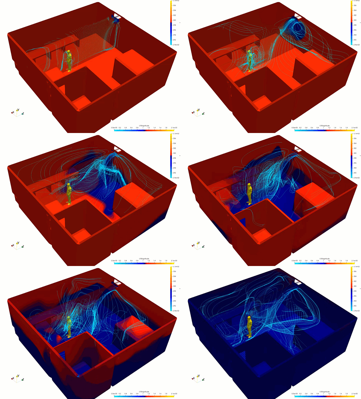
HVAC systems in commercial office spaces are critical operational assets responsible for maintaining thermal comfort and indoor air quality while minimizing energy consumption. While steady-state analysis is useful for baseline sizing, it fails to capture real-world dynamic shifts—such as rapid changes in outdoor weather, sudden occupancy surges during meeting hours, or the morning startup sequence of the heating and cooling loops. Operating under unoptimized transient conditions leads to uncomfortable thermal lagging, localized stuffiness, and severe energy spikes. Computational Fluid Dynamics (CFD) provides building services engineers with a dynamic virtual environment to trace time-dependent airflow paths, monitor localized temperature shifts, and refine control strategies with high precision.
Technical and Theoretical Description
From a building physics perspective, a transient HVAC case operates on coupled, time-dependent buoyancy-driven internal aerodynamics governed by the three-dimensional, incompressible Navier-Stokes equations and the energy equation. The air distribution and temperature field evolve over a defined time domain, driven by changing boundary conditions. Because indoor airflow features low-velocity circulation interspersed with high-velocity jets from diffuser supply grilles, CFD simulations utilize advanced turbulence models. The Reynolds-Averaged Navier-Stokes (RANS) Shear Stress Transport (k-omega SST) model is widely used due to its ability to resolve boundary layer separation along walls, ceilings, and human surfaces under changing conditions.
The primary theoretical focus in transient HVAC modeling is tracking Conjugate Heat Transfer (CHT) and species transport across the occupied space. Thermal energy enters or leaves the fluid domain through solid-to-fluid convection and surface-to-surface radiation, which is resolved using the Discrete Ordinates (DO) radiation model to account for solar heat gain through glass windows. Heat transfer via conduction through multi-layered concrete walls and insulation is solved via Fourier’s Law using time-dependent thermal mass profiles. The core comfort metrics evaluated are the Predicted Mean Vote (PMV) and Predicted Percentage of Dissatisfied (PPD), which are defined by plain-text mathematical empirical relations that factor in localized air velocity, temperature, relative humidity, clothing insulation, and metabolic rates. Concurrently, to evaluate indoor air quality during an occupancy surge, a passive scalar species transport equation is solved to map carbon dioxide (CO2) accumulation and tracking over time.
Business Value of CFD Implementation
From a commercial viewpoint, deploying transient CFD in building envelope design yields massive capital expenditure (CapEx) savings and heavily reduces commercial operational expenditures (OpEx). Historically, mechanical engineers relied on overly conservative safety factors, resulting in the over-specification and purchasing of oversized chillers, boilers, and air handling units (AHUs). Transient CFD acts as a high-fidelity virtual staging ground, allowing design teams to accurately determine the minimum mechanical capacity needed to handle peak load shifts, safely right-sizing equipment and cutting upfront asset procurement costs.
In terms of OpEx, a transiently refined HVAC system directly slashes corporate energy bills and enhances workspace productivity. Inefficient morning purge cycles—where an empty building is aggressively cooled or heated before employees arrive—consume enormous amounts of power. CFD optimization allows facility management to implement smart, staggered startup routines that leverage the building’s inherent thermal mass, lowering peak demand electrical charges. Furthermore, eliminating localized thermal lag prevents worker discomfort, which is directly linked to cognitive performance and operational productivity, thereby maximizing the commercial yield of the real estate asset.
Challenges of CFD in Transient HVAC Modeling
Despite its analytical power, simulating transient HVAC behavior introduces steep computational and physical scale challenges. The foremost obstacle is managing the vastly different timescales involved in the coupled physics. Fluid flow across an office occurs in seconds, requiring small numerical time-steps to maintain stability, yet the thermal mass response of heavy concrete walls and changing solar positions unfolds over several hours. Running a full-scale, multi-hour transient simulation with tiny time-steps demands immense computational processing power and generates massive data volumes.
Another major hurdle is accurately characterizing highly variable, dynamic boundary conditions. Occupant movement, electronic equipment usage, and solar radiation profiles are highly erratic. If the simulation simplifies these inputs into static averages, it completely misses the transient temperature spikes that trigger thermal discomfort. Furthermore, modeling buoyancy-driven flows under low-velocity conditions requires a highly stable pressure-velocity coupling mechanism; any minor numerical imbalance in the density-temperature source term can cause artificial numerical oscillations, ruining the validity of the thermal comfort predictions.
Solutions for High-Fidelity Simulation
To overcome these transient scale and coupling challenges, modern building engineering workflows utilize specialized time-stepping methods and smart boundary configurations. Engineers resolve the timescale discrepancy by deploying dual-time stepping schemes or frozen-flow approximations, where the fluid velocity field is calculated at larger intervals while the energy and thermal conduction equations are solved at a finer frequency. Real-world climate data and solar path tracking are integrated into the simulation via time-dependent profile tables or customized user-defined functions (UDFs) that automatically update boundary conditions hour by hour.
The computational domain is constructed using high-quality hexahedral or polyhedral meshes, with grid refinement concentrated at supply diffusers, return grilles, and near human boundaries where steep velocity and thermal gradients exist. Thermal properties of occupants are represented as lumped heat source models with moving boundary approximations if pedestrian foot traffic must be accounted for. Finally, to eliminate identified thermal lag or stuffiness, engineers use the CFD environment to virtually iterate smart control loops, such as testing Variable Air Volume (VAV) responsive throttling or shifting diffuser placements. Validating the success of these dynamic control changes in software guarantees an energy-efficient, responsive, and comfortable indoor workspace blueprint before physical building construction or HVAC retrofitting.
Author: Caesar Wiratama
Find me on Linkedin