
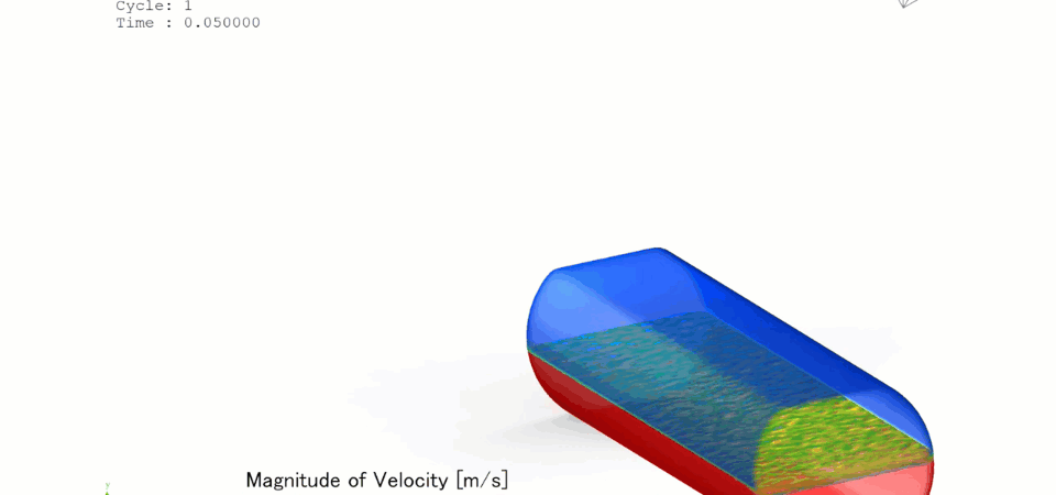
Liquid sloshing inside storage tanks is a critical safety and structural risk across the marine transit, aerospace, automotive, and civil engineering sectors. When partially filled tanks experience sudden accelerations—such as a liquefied natural gas (LNG) tanker navigating rough seas, a spacecraft maneuvering in orbit, or a water tower enduring seismic activity—the internal liquid moves violently. This sloshing creates severe, localized hydrodynamic pressure spikes against the tank walls and introduces large, destabilizing dynamic forces that can compromise vehicular control or cause structural failure. Computational Fluid Dynamics (CFD) provides structural and naval engineers with a high-fidelity digital wave tank to visualize transient free-surface behavior, compute localized impact pressures, and refine internal suppression geometries with extreme precision.
Technical and Theoretical Description
From a physical perspective, a sloshing tank operates on highly transient, multi-phase fluid dynamics characterized by large free-surface deformations, violent wave-breaking, and gas entrapment. The flow field within the tank is governed by the three-dimensional, compressible or incompressible Navier-Stokes equations coupled with the energy equation. Because the motion of the tank generates severe liquid-wall impacts, flow separation, and intense churning, CFD simulations utilize advanced transient turbulence closures. The Reynolds-Averaged Navier-Stokes (RANS) Shear Stress Transport (k-omega SST) model is universally applied to resolve near-wall boundary layers, while Scale-Adaptive Simulation (SAS) or Large Eddy Simulation (LES) is deployed for high-fidelity capturing of chaotic, breaking wave fronts.
A primary theoretical focus in sloshing analysis is tracking the moving interface between the liquid product and the overhead gas blanket. This is achieved using the Volume of Fluid (VOF) method, which tracks the volume fraction of each phase in every computational cell. To simulate real-world movement, the computational domain is subjected to forced translational and rotational accelerations via user-defined motion equations that mirror structural or environmental frequencies. The core metrics evaluated are the total hydrodynamic forces and moments exerted on the tank structure, along with the peak impact pressures during wave slamming. Capturing the sudden compression of entrapped gas pockets between the rising wave crest and the tank roof is critical, as this compression generates localized pressure pulses that can trigger material fatigue or fracture.
Business Value of CFD Implementation
From a commercial viewpoint, deploying CFD to analyze and suppress liquid sloshing yields massive capital expenditure (CapEx) savings and significantly reduces structural risk. Building physical scale models equipped with high-speed pressure sensors and shaking tables is a highly restricted, capital-intensive process that cannot easily replicate extreme high-velocity sloshing without significant scaling errors. CFD serves as a rapid virtual test rig, allowing design teams to test dozens of tank geometries and internal baffles in software, compressing the engineering design timeline and avoiding the massive costs of post-construction structural failures.
In terms of operational expenditures (OpEx), a refined tank design directly translates to enhanced vehicle stability and safety. For marine transport companies, minimizing the sloshing-induced moments on LNG tankers reduces the risk of capsizing and prevents structural damage to the tank’s internal cryogenic insulation containment systems. For aerospace applications, suppressing fuel sloshing eliminates unwanted center-of-gravity shifts that can confuse rocket guidance systems and lead to mission failure. Ultimately, CFD transforms tank engineering from a conservative, over-designed framework into an optimized strategy that maximizes cargo volume while safeguarding structural integrity and operational safety.
Challenges of CFD in Sloshing Tank Modeling
Despite its analytical power, simulating fluid sloshing introduces steep physical and numerical challenges. The foremost obstacle is the highly chaotic and discontinuous nature of breaking waves. When a liquid wave breaks or impacts a solid boundary, it shatters into a multi-scale mixture of droplets, spray, and entrapped air bubbles. Resolving these localized, micro-scale multiphase features requires ultra-fine mesh densities and immense computational power. If the mesh is too coarse, numerical diffusion artificially dampens the wave energy, leading to underpredicted peak impact pressures and invalidating safety margin assessments.
Another major hurdle is managing numerical stability over long-duration transient simulations. Sloshing events are evaluated over hundreds of oscillation cycles to identify resonance conditions where the fluid’s natural frequency matches the vehicle’s movement frequency. Maintaining a low Courant number across these long durations requires incredibly small time-steps, which vastly increases the processing time. Furthermore, capturing the rapid transition between compressible gas behavior and incompressible liquid impacts at the boundaries demands highly robust numerical pressure-velocity coupling algorithms that are prone to divergence if the grid quality deteriorates near sharp corners.
Solutions for High-Fidelity Simulation
To overcome these transient multiphase and scale challenges, modern engineering workflows combine advanced spatial discretization with specialized boundary-tracking features. Engineers resolve localized wave-breaking and impact zones by utilizing unstructured polyhedral or hex-dominant grids paired with automated Adaptive Mesh Refinement (AMR). The AMR algorithm dynamically densifies the mesh along the air-water interface and near the tank ceiling based on localized volume fraction gradients, ensuring high-resolution tracking of wave crests without over-meshing stagnant zones.
To handle forced tank motion without destroying mesh quality or triggering numerical instability, simulations utilize Arbitrary Lagrangian-Eulerian (ALE) formulations, sliding meshes, or overset (chimera) grid techniques. These methods allow the internal boundaries to move or rotate smoothly through the computational domain while tracking real-time accelerations. Finally, to eliminate identified sloshing hazards, engineers use the CFD environment to virtually iterate structural counter-measures. This includes testing the addition of perforated vertical baffles, horizontal ring baffles, or elastic membrane dividers. By extracting the transient pressure loads from the fluid solver and mapping them onto Finite Element Analysis (FEA) software via Fluid-Structure Interaction (FSI) workflows, structural engineers can verify the final tank blueprint’s resistance to dynamic cyclic stress prior to steel fabrication or ship construction.
Author: Caesar Wiratama
Find me on Linkedin