
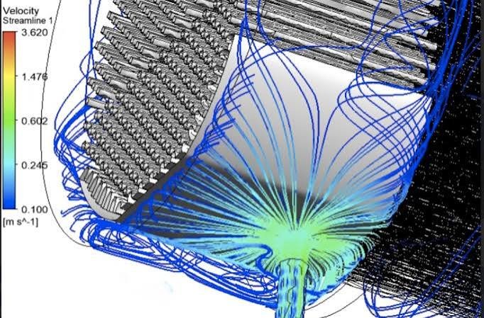
Shell and tube heat exchangers are vital thermal management assets heavily utilized in petroleum refining, chemical processing, and power generation to transfer heat between two high-pressure fluid streams. Because these units frequently process fluids containing abrasive suspended solids or operate at localized velocities high enough to trigger liquid droplet impingement, they are exceptionally prone to mechanical erosion. Over time, erosion degrades internal components, leading to tube punctures, fluid cross-contamination, and catastrophic unscheduled plant shutdowns. Computational Fluid Dynamics (CFD) provides mechanical and reliability engineers with a non-destructive digital laboratory to visualize localized velocity spikes, track particle trajectories, and refine internal geometries with high precision.
Technical and Theoretical Description
From a fluid mechanics perspective, erosion within a shell and tube heat exchanger operates on highly complex multiphase dynamics governed by the three-dimensional Navier-Stokes equations coupled with discrete particle kinematics. Fluids passing through the shell side navigate a labyrinth of baffles, tube bundles, and sealing strips, creating intensely turbulent flow fields with sharp directional changes. To accurately capture these complex flow paths and localized velocity gradients, CFD simulations utilize advanced turbulence models, most notably the Reynolds-Averaged Navier-Stokes (RANS) Shear Stress Transport (k-omega SST) or Realizable k-epsilon models due to their precision in resolving boundary layers and flow separation.
To model the physical wear on internal surfaces, engineers couple the continuous fluid flow field with the Discrete Phase Model (DPM) using Eulerian-Lagrangian tracking. This approach tracks individual abrasive particles or droplets by applying Newton’s second law, calculating the balance of hydrodynamic drag, gravity, buoyancy, and virtual mass forces. The localized material volume loss is then quantified using empirical erosion models integrated into the wall boundary conditions, such as the Oka or McLaury erosion formulations. These equations calculate material wear as a function of plain-text variables: impact velocity, particle impingement angle, particle diameter, and the hardness of the target metal. The simulation monitors critical structural regions—specifically the shell-side inlet nozzle, the initial rows of the tube bundle directly facing the incoming flow, and the tube-to-tubesheet joints—where localized shear stresses and particle impacts are most concentrated.
Business Value of CFD Implementation
From a commercial standpoint, deploying CFD to analyze and mitigate heat exchanger erosion yields massive capital expenditure (CapEx) savings and directly drives down plant operational expenditures (OpEx). In the design or asset retrofitting phase, CFD serves as a rapid virtual prototyping environment. Engineers can evaluate dozens of impingement plate designs, baffle spacings, and nozzle configurations in software, compressing the engineering design timeline and avoiding the massive financial risks of manufacturing faulty physical machinery.
In terms of OpEx, a refined internal flow distribution directly maximizes the operational lifespan of the heat exchanger. Identifying and eliminating localized high-velocity zones prevents premature tube thin-out and unexpected tube leaks, which slashes the frequency of expensive, unscheduled maintenance shutdowns and avoids costly fluid cross-contamination events. Furthermore, optimizing the internal geometry through CFD ensures that velocity thresholds are maintained safely below the material’s critical erosion-corrosion limits without introducing excessive pressure drops. This minimizes the parasitic power consumption of upstream pumps, delivering substantial annual utility savings and maximizing the asset’s overall return on investment.
Challenges of CFD in Heat Exchanger Erosion Modeling
Despite its analytical power, simulating erosion inside a shell and tube heat exchanger introduces steep multi-scale physical and numerical challenges. The foremost obstacle is the extreme geometric scale discrepancy coupled with high mesh requirements. A heavy industrial heat exchanger can stretch across several meters and contain thousands of individual tubes, yet capturing the millimeter-scale gaps between tubes, baffles, and the shell wall requires an immense cell count. Attempting to fully resolve the turbulent boundary layers around thousands of tubes in a single macro-scale simulation generates an unmanageable mesh count that demands massive computational infrastructure.
Another major hurdle is accurately capturing the non-linear physics of multi-particle interactions and variable particle shapes. Real-world industrial slurry or ash particles are rarely uniform spheres; they possess highly irregular, sharp geometries that dramatically alter their drag coefficients and impact behaviors. Furthermore, in high-concentration zones near the inlet nozzle, particles collide with one another—a phenomenon known as four-way phase coupling—which alters their trajectories before they strike the metal walls. Simulating these transient particle-to-particle interactions and localized chaotic bouncing sequences requires highly sensitive numerical tracking algorithms that are prone to divergence if the boundary meshes or time steps are poorly managed.
Solutions for High-Fidelity Simulation
To overcome these multi-scale and multiphase challenges, modern mechanical engineering workflows combine advanced spatial discretization with specialized sub-grid physical models. Engineers resolve the massive scale discrepancy by utilizing multi-zone meshing techniques. Instead of meshing the entire length of thousands of identical tubes, the core tube bundle is modeled using anisotropic porous media zones calibrated via empirical pressure drop data, while the critical, erosion-prone inlet and outlet regions are fully resolved using high-density polyhedral or hex-dominant meshes with tight prism layer inflation along the tube walls.
To handle irregular particle shapes and high-concentration zones efficiently, simulations utilize advanced non-spherical drag laws (such as the Haider-Levenspiel formulation) combined with dense particle tracking methods like the Multiphase Particle-in-Cell (MPIC) approach. This allows the software to track computational particle parcels while mathematically accounting for inter-particle collisions and volume-fraction effects. Finally, to eliminate identified erosion risks, engineers use the CFD environment to virtually iterate flow-correcting modifications, such as introducing perforated distributor plates, adding dome-shaped impingement baffles, or expanding the inlet nozzle diameter. Validating the success of these geometric changes in software guarantees a balanced, highly uniform flow field that effectively neutralizes erosion risks before physical manufacturing begins.
Author: Caesar Wiratama
Find me on Linkedin