
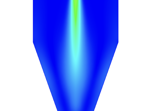
Gas-fired milk boilers, or pasteurizers, are safety-critical thermal assets widely used in the dairy processing industry to heat raw milk to exact pasteurization temperatures. The fundamental engineering challenge in processing dairy is extreme heat sensitivity: the fluid must be heated rapidly to eliminate pathogens, but if the internal wall temperature gets too high, the milk proteins denature and bake onto the surface—a costly phenomenon known as fouling. Computational Fluid Dynamics (CFD) provides dairy process engineers with an indispensable virtual testing environment to analyze fluid paths, map conjugate heat transfer, and eliminate localized thermal hotspots with extreme precision.
Technical and Theoretical Description
From a physical and chemical perspective, a gas-fired milk boiler operates on heavily coupled, multi-mode heat transfer governed by the three-dimensional, compressible Navier-Stokes equations and the energy equation. The system involves two main domains: the combustion side (where natural gas or propane reacts with air) and the fluid side (where the milk flows through tubes or channels). Because the high-velocity combustion gases and the moving milk operate under highly turbulent regimes, CFD simulations utilize advanced turbulence models, most notably the Shear Stress Transport (k-omega SST) model, due to its superior accuracy in predicting thermal boundary layer development along curved solid walls.
The core theoretical focus in dairy boiler modeling is Conjugate Heat Transfer (CHT), which solves the thermal interaction between the hot combustion gas, the metallic exchanger wall, and the liquid milk simultaneously. Heat transfer is quantified using Fourier’s Law for solid conduction and Newton’s Law of Cooling for convection. Because milk is a non-Newtonian, temperature-dependent fluid, its viscosity must be modeled using customized rheological formulations, such as the Herschel-Bulkley or Power Law models, where fluid viscosity drops as the shear rate and temperature increase. Furthermore, to track the chemical kinetics of fouling, empirical protein denaturation equations are implemented as wall boundary source terms to mathematically predict where and how fast an insulating layer of milk solids will accumulate on the pipes over time.
Business Value of CFD Implementation
From a commercial viewpoint, deploying CFD to analyze and refine milk boilers yields massive capital expenditure (CapEx) savings and directly protects product quality. Fabricating physical stainless-steel sanitary heat exchangers and testing them with real dairy products is an incredibly expensive process that results in significant product waste. CFD serves as a rapid virtual prototyping environment, allowing design teams to iterate through dozens of dimpled plate patterns, tube bundle pitches, and burner geometries in software, compressing the engineering timeline from months to weeks.
In terms of operational expenditures (OpEx), CFD optimization directly reduces factory downtime and utility costs. Identifying and eliminating localized hot spots prevents protein scorching, which significantly extends the operational runtime of the boiler between cleaning cycles. This slashes the consumption of expensive Clean-in-Place (CIP) chemicals and minimizes water usage. Furthermore, by optimizing the internal flow paths to minimize pressure drop while maximizing heat transfer efficiency, the boiler consumes less natural gas, delivering massive annual energy savings and a rapid return on investment for the processing facility.
Challenges of CFD in Milk Boiler Modeling
Despite its analytical power, simulating a gas-fired milk boiler introduces steep multi-scale physical and numerical challenges. The foremost obstacle is the extreme non-linearity of the coupled physics. The simulation must resolve the high-temperature combustion reactions occurring in the gas burners alongside the low-temperature, highly viscous flow of the dairy fluid on the other side of a millimeter-thin metal wall. Managing these vast temperature and velocity gradients requires a highly dense mesh along the fluid-solid interfaces.
Another major hurdle is the transient modeling of the fouling layer itself. As denatured proteins bake onto the inner pipe surfaces, they form an insulating barrier that possesses a much lower thermal conductivity than the stainless steel wall. This layer continuously changes the internal geometry and reduces the heat transfer rate over time. Simulating this dynamic, time-dependent growth requires moving boundary algorithms or transient cell-deactivation techniques that can become computationally prohibitive and numerically unstable if the grid resolution or time steps are poorly managed.
Solutions for High-Fidelity Simulation
To overcome these non-linear and multi-scale challenges, modern dairy engineering workflows combine advanced meshing strategies with specialized chemical sub-models. Engineers resolve the geometric scale discrepancies by utilizing high-quality hexahedral or polyhedral grids, with heavy grid refinement and tight prism layer inflation concentrated along the internal pipe walls to perfectly capture the thermal boundary layers. Combustion zones are solved using accelerated chemistry frameworks, such as the Eddy Dissipation Concept (EDC), to provide accurate flue gas temperature profiles before tracking heat flux into the milk domain.
To handle the complex fouling phenomenon without overwhelming computational budgets, steady-state CHT simulations are paired with decoupled, time-step-driven wall-fouling models. The software calculates the localized wall shear stress and temperature, uses those metrics to compute the protein deposition rate, and then updates the local thermal resistance of the wall dynamically. Finally, to eliminate identified thermal hotspots, engineers utilize the CFD environment to virtually iterate flow-correcting devices, such as adding internal tube twisted-tape inserts or optimizing the burner flame length. Validating these modifications digitally guarantees a highly efficient, gentle, and low-maintenance pasteurization blueprint before physical manufacturing begins.
Author: Caesar Wiratama
Find me on Linkedin