
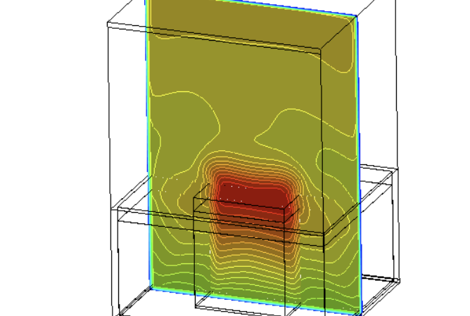
Spent fuel storage racks are safety-critical infrastructure assets housed within wet storage pools at nuclear power plants to isolate and cool highly radioactive used fuel assemblies. Even after being removed from the reactor core, spent nuclear fuel continues to generate significant decay heat from ongoing radioactive decay. If this heat is not continuously and uniformly dissipated, the pool water can boil, exposing the fuel rods and risking structural degradation or a severe radiological release. Computational Fluid Dynamics (CFD) provides nuclear thermal engineers with a non-destructive digital environment to analyze natural convection paths, eliminate localized thermal hotspots, and validate passive cooling safety margins with absolute precision.
Technical and Theoretical Description
From a thermal-hydraulic standpoint, a spent fuel rack operates on heavily coupled, buoyancy-driven natural convection and multi-mode heat transfer governed by the three-dimensional Navier-Stokes and energy equations. Unlike forced-circulation loops, the fluid flow through the tight, vertical storage cells is entirely passive. It is driven by the density differences between the cold water entering the bottom of the rack and the heated water rising through the fuel assemblies. Because the velocity fields are relatively low but can exhibit localized turbulent plumes at the exit of the assemblies, CFD simulations utilize advanced low-Reynolds number turbulence models, most notably the Shear Stress Transport (k-omega SST) model, to accurately capture boundary layer development along the fuel rod skins.
A core theoretical requirement in this application is the accurate representation of the fuel assembly geometry. A single spent fuel rack can contain hundreds of assemblies, each comprising a dense matrix of fuel pins and spacer grids. Fully resolving this geometry is computationally prohibitive. Instead, engineers model the fuel assembly region as an anisotropic porous media zone. The directional flow resistance coefficients (inertial and viscous resistance parameters) are calculated mathematically based on empirical pressure drop correlations or separate high-fidelity sub-channel simulations. Heat transfer from the fuel rods to the water is governed by Newton’s Law of Cooling, implemented via a distributed volumetric heat source term within the porous zone. This heat source decreases over time according to radioactive decay heat curves defined by plain-text mathematical functions.
Business Value of CFD Implementation
From a commercial and regulatory perspective, deploying CFD in spent fuel rack design yields massive capital expenditure (CapEx) savings and directly accelerates utility approval cycles. Nuclear safety authorities enforce strict thermal design criteria, demanding absolute proof that maximum fuel cladding temperatures remain safely below critical thresholds under all operational and accident scenarios. Performing physical, full-scale thermal tests on radioactive equipment is impossible, and electrical mock-ups are exceptionally expensive. CFD serves as the primary analytical tool to demonstrate compliance, allowing engineering companies to secure regulatory licensing and speed up plant construction or license renewal timelines.
In terms of operational expenditures (OpEx), high-fidelity CFD models enable “reracking” projects that maximize the storage density of existing spent fuel pools. By accurately mapping the natural circulation flow paths, engineers can safely minimize the spacing between storage cells without exceeding temperature limits. This eliminates the multi-million dollar need to build separate, away-from-reactor dry storage facilities prematurely. Furthermore, characterizing the exact temperature distribution across the pool allows plant operators to optimize the cooling duty of the pool’s external heat exchangers, reducing parasitic auxiliary power consumption and lowering long-term plant maintenance costs.
Challenges of CFD in Spent Fuel Rack Modeling
Despite its analytical power, simulating a nuclear spent fuel rack introduces steep multi-scale physical and numerical challenges. The foremost obstacle is the extreme geometric scale discrepancy coupled with weak buoyancy forces. A spent fuel pool stretches across tens of meters, while the fluid channels between individual fuel rods and the clearance gaps at the base of the racks are measured in millimeters. Resolving the global macro-circulation of the pool alongside these micro-scale flow pathways requires highly strategic spatial discretization to keep mesh sizes within practical computational limits.
Another major hurdle is the highly non-linear nature of natural convection driving forces. Because the fluid velocity is directly coupled to temperature-induced density changes, any small numerical error in the localized temperature field immediately distorts the computed buoyancy force, leading to non-convergence or unphysical flow oscillations. Furthermore, under extreme accident conditions—such as a complete loss of external pool cooling—the water temperature can reach the saturation point. Simulating the subsequent transient subcooled boiling, bubble formation, and two-phase vapor-liquid tracking requires highly sensitive multiphase algorithms that are exceptionally prone to numerical instability.
Solutions for High-Fidelity Simulation
To overcome these multi-scale and buoyancy coupling challenges, modern nuclear engineering workflows combine advanced meshing strategies with specialized numerical stabilization features. Engineers resolve the scale discrepancy by utilizing structured hexahedral or high-quality polyhedral grids, with heavy mesh refinement concentrated at the rack inlet plenums, outlet chimneys, and near the pool walls where steep thermal gradients occur. The Boussinesq approximation is applied for steady-state thermal evaluations, while fully temperature-dependent fluid density definitions are utilized for transient accident simulations to ensure the buoyancy source terms are computed with high fidelity.
To handle complex layout variations efficiently, simulations utilize symmetric or periodic boundary conditions when modeling full-pool configurations, focusing computational resources on critical quadrants. For high-fidelity accident analysis involving phase changes, advanced Eulerian multiphase models are paired with sub-grid boiling models to track vapor generation rates safely. Finally, the calculated localized temperature and pressure fields are exported directly into Finite Element Analysis (FEA) software. This fluid-structure interaction (FSI) workflow allows structural engineers to verify that the structural steel of the racks will not warp, buckle, or suffer from thermal-stress cracks under maximum thermal loading, finalizing a robust and safe storage blueprint before physical implementation.
Author: Caesar Wiratama
Find me on Linkedin