
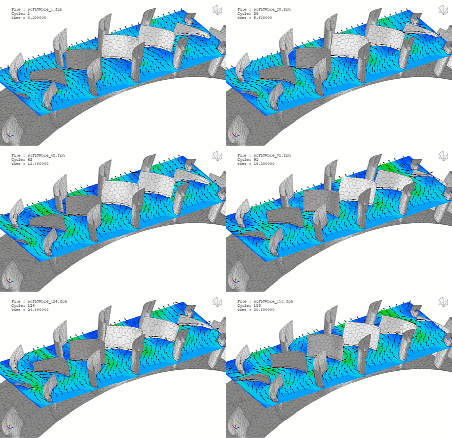
Axial gas turbine blades are among the most highly stressed components in aerospace propulsion and industrial power generation. Operating directly in the path of high-temperature, high-pressure combustion exhaust, these blades must withstand extreme centrifugal forces while extracting maximum kinetic energy from the fluid stream. The engineering challenge is exceptionally demanding: designers must maximize aerodynamic efficiency while keeping blade temperatures well below the melting point of their advanced superalloys. Computational Fluid Dynamics (CFD) provides turbomachinery engineers with an indispensable virtual test rig to visualize complex 3D flow fields, evaluate aerodynamic losses, and optimize internal and external cooling configurations with extreme precision.
Technical and Theoretical Description
From a turbomachinery perspective, an axial gas turbine blade operates on highly complex, three-dimensional external and internal fluid dynamics governed by the compressible Navier-Stokes and energy equations. The flow field around a rotating blade row is characterized by high Mach numbers, transonic flow regimes, shock wave formations, and intense boundary layer interactions. To accurately capture these complex flow features, CFD simulations utilize transient formulations within a rotating frame of reference. This is achieved using the Multiple Reference Frame (MRF) approach for steady-state approximations or the transient Sliding Mesh and Mixing Plane methods for time-dependent stage interactions. Turbulence is modeled using advanced closures like the Reynolds-Averaged Navier-Stokes (RANS) Shear Stress Transport (k-omega SST) model, often paired with transition models (such as the gamma-Re_theta model) to precisely predict where the laminar boundary layer transitions to turbulent flow on the blade surface.
A critical theoretical focus in modern blade design is the modeling of Conjugate Heat Transfer (CHT) to evaluate film and internal cooling performance. Because the gas temperatures entering the turbine stage often exceed the blade’s material limits, blades utilize complex internal cooling passages featuring turbulators, pin-fins, and dimples to maximize heat extraction via internal convection. Concurrently, a fraction of the cooling air is discharged through rows of micro-holes along the blade skin, forming a protective, insulating layer of cool air—a phenomenon known as film cooling. CFD tracks this multi-stream interaction by solving the fluid and solid domains simultaneously, allowing engineers to calculate the cooling effectiveness across the blade. Aerodynamic loss metrics, such as the total pressure loss coefficient and aerodynamic stage efficiency, are continuously evaluated alongside structural pressure loading profiles to optimize the 3D twist, lean, and flare of the blade profile.
Business Value of CFD Implementation
From a commercial standpoint, integrating CFD into axial gas turbine blade engineering yields massive capital expenditure (CapEx) savings and significantly compresses product time-to-market. Manufacturing prototype turbine blades requires high-precision investment casting of single-crystal superalloys and specialized EDM drilling for cooling holes, costing tens of thousands of dollars per blade design. CFD acts as a rapid virtual prototyping environment, allowing design teams to iterate through hundreds of airfoil shapes, blade twists, and film cooling hole geometries in software before committing to expensive physical tooling.
In terms of operational expenditures (OpEx), an optimized turbine blade directly maximizes fuel efficiency and extends asset service life. Elevating the turbine inlet temperature directly increases thermodynamic efficiency; however, every 10-degree Celsius reduction in localized blade peak temperature achieved through CFD optimization can double the operating lifespan of the blade before it suffers from creep or thermal fatigue. This drastically reduces the frequency of incredibly expensive hot-gas path inspections, component replacements, and forced outages for utility companies and commercial airlines. Ultimately, CFD transforms the blade from a conservative, life-limited component into a highly optimized, high-yielding asset.
Challenges of CFD in Turbine Blade Modeling
Despite its analytical power, simulating an axial gas turbine blade introduces steep multi-scale physical and numerical challenges. The foremost obstacle is the extreme geometric and physical scale discrepancy. A turbine blade may span tens of centimeters, yet the boundary layer fluid physics, shock wave interactions, tip leakage flows, and film cooling holes require micron-scale mesh resolution to resolve the intense localized gradients. Fully meshing a complete turbine stage with hundreds of film cooling holes generates an unmanageable mesh count that demands massive computational infrastructure.
Another major hurdle is modeling the high-frequency transient interactions between the stationary stator vanes and rotating rotor blades. As the blades pass through the wakes of the upstream vanes, they experience highly unsteady aerodynamic forces, shock-boundary layer interactions, and cyclic thermal throttling. Simulating these transient phenomena with high fidelity requires incredibly fine time-steps and robust numerical stabilization. Furthermore, capturing the exact trajectory and mixing behavior of the coolant jets as they exit the angled film cooling holes into a high-crossflow, swirling environment remains a highly non-linear boundary tracking challenge that is prone to numerical diffusion if poorly configured.
Solutions for High-Fidelity Simulation
To overcome these multi-scale and transient challenges, modern turbomachinery workflows combine advanced spatial discretization with highly optimized solver features. Engineers resolve the scale discrepancy of film cooling holes by utilizing non-uniform, unstructured polyhedral meshes paired with automated Adaptive Mesh Refinement (AMR) in regions experiencing steep temperature and velocity gradients. For full-wheel or multi-stage simulations where resolving every cooling hole explicitly is computationally prohibitive, specialized sub-grid film cooling boundary models are applied to inject coolant mass, momentum, and energy directly into the fluid domain based on empirical discharge coefficients.
To handle transient stage interactions efficiently without modeling the entire 360-degree rotor wheel, simulations deploy specialized periodic boundary conditions and time-transformation methods, such as the Time-Spectral or Phase-Lag techniques. These tools allow the software to process unsteady periodic flows using a fraction of the computational resources required for full-annulus transient simulations. Finally, the extracted transient aerodynamic pressure fields and CHT temperature distributions are mapped directly onto structural grids via Fluid-Structure Interaction (FSI) workflows. This enables structural engineers to perform high-fidelity Finite Element Analysis (FEA) to verify centrifugal stress limits, creep life, and vibrational resonance frequencies, ensuring a robust and reliable blade blueprint prior to manufacturing.
Author: Caesar Wiratama
Find me on Linkedin