
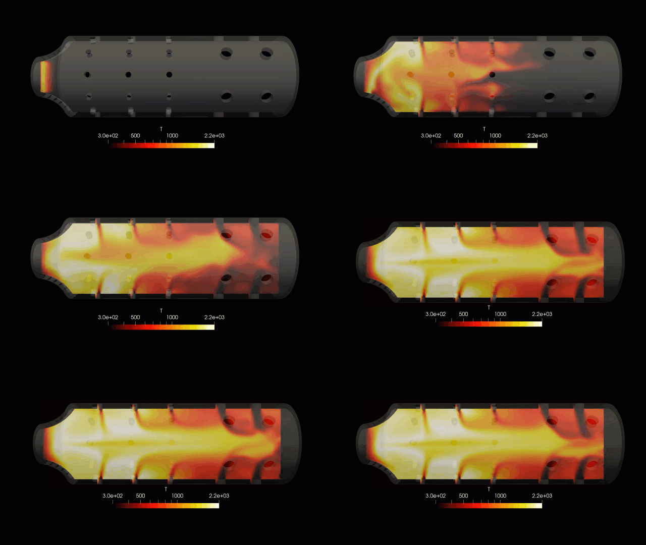
Combustion chambers are the high-energy core assets of gas turbines, jet engines, and advanced industrial furnaces. Operating under extreme thermodynamic conditions, these components must rapidly mix fuel and air to sustain a stable, high-intensity flame while maximizing thermal efficiency. The engineering challenge is exceptionally demanding: designers must minimize pollutant emissions such as nitrogen oxides (NOx) and carbon monoxide (CO), prevent flame blowout, and ensure uniform temperature profiles to protect downstream turbine blades. Computational Fluid Dynamics (CFD) provides combustion engineers with an indispensable virtual test rig to visualize highly swirling reactive flows, assess chemical kinetics, and optimize liner geometries with extreme precision.
Technical and Theoretical Description
From a fluid mechanics and chemical perspective, a combustion chamber operates on highly coupled, compressible, reacting fluid dynamics governed by the three-dimensional Favre-Averaged Navier-Stokes equations, the energy equation, and multi-component species transport equations. Fluid flow within the chamber is intensely turbulent, driven by specialized swirlers designed to create a central toroidal recirculation zone that stabilizes the flame. To capture these highly anisotropic turbulent flow structures and vortex breakdown, CFD simulations utilize advanced transient modeling. While the Reynolds-Averaged Navier-Stokes (RANS) Re-Normalization Group (RNG) k-epsilon or Shear Stress Transport (k-omega SST) models are used for initial design screening, high-fidelity Large Eddy Simulation (LES) is increasingly applied to resolve large-scale turbulent fluctuations that drive combustion instabilities.
The transformation of chemical fuel energy into thermal energy is modeled using sophisticated turbulence-chemistry interaction (TCI) frameworks. For gaseous or liquid spray fuels, the chemistry is often solved using the Flamelet Generated Manifold (FGM) or Eddy Dissipation Concept (EDC) models, coupled with detailed skeletal reaction mechanisms. In liquid-fueled combustors, Eulerian-Lagrangian tracking is deployed to simulate the discrete spray phase. This involves tracking liquid droplets through secondary breakup models (such as the Taylor Analogy Breakup model) and evaporation physics governed by the Spalding mass transfer number. Thermal radiation is computed using the Discrete Ordinates (DO) model to accurately predict localized wall heat fluxes. Concurrently, pollutant pathways are solved using specialized chemical kinetic sub-models to track prompt, thermal, and nitrous oxide NOx formation across the reacting domain.
Business Value of CFD Implementation
From a commercial standpoint, integrating CFD into the combustion chamber development lifecycle yields massive capital expenditure (CapEx) savings and significantly compresses product time-to-market. Building and testing physical combustion rigs requires specialized high-pressure, high-temperature laboratories and expensive optical diagnostic equipment. CFD acts as a rapid virtual prototyping environment, allowing engineering teams to test dozens of swirl angles, dilution hole patterns, and fuel injector designs in software, slashing upfront R&D expenditures.
In terms of operational expenditures (OpEx), an optimized combustion chamber design directly enhances asset reliability and fuel flexibility. Achieving a highly uniform temperature distribution at the combustor exit—quantified as a low Pattern Factor—minimizes thermal fatigue on expensive downstream turbine blades, extending their service life and reducing forced maintenance outages. Furthermore, CFD optimization allows manufacturers to safely adapt their combustors for alternative fuels, such as hydrogen blends or biofuels, without risking physical engine hardware. This enables operators to meet strict global emissions compliance standards while maximizing the long-term commercial viability of the asset.
Challenges of CFD in Combustor Modeling
Despite its analytical power, simulating a combustion chamber introduces steep multi-scale physical and numerical challenges. The foremost obstacle is the extreme non-linearity and stiffness of the governing equations. The chemical reactions occur at microsecond timescales within sub-millimeter flame fronts, while the macroscopic aerodynamic mixing and swirler flow field span meters. Resolving this intense multi-scale coupling requires immense computational power and ultra-fine mesh densities.
Another major hurdle is modeling transient thermoacoustic combustion instabilities. These occur when unsteady heat release rates couple constructively with the acoustic modes of the combustion chamber, generating violent pressure oscillations that can structurally destroy the combustor liner or fuel nozzles. Simulating these high-frequency acoustic waves and phase-locked heat release variations demands fully compressible LES solvers with strict time-stepping control. Furthermore, capturing the complex, transient phase-change physics of liquid fuel atomization—where a continuous fuel jet shatters into a cloud of microscopic droplets—remains a highly non-linear boundary tracking challenge.
Solutions for High-Fidelity Simulation
To overcome these reacting flow and multi-scale challenges, modern aerospace and power-generation workflows combine advanced spatial discretization with highly optimized solver architectures. Engineers resolve geometric scale discrepancies by utilizing high-quality polyhedral or hex-dominant meshes, applying extreme grid refinement around fuel nozzles, swirler vanes, and the primary combustion zone, often enhanced by automated Adaptive Mesh Refinement (AMR). Liquid fuel sprays are categorized into realistic statistical size distributions using the Rosin-Rammler diameter formulation to ensure accurate evaporation profiles.
To handle transient thermoacoustic phenomena and stiff chemical kinetics, fully compressible transient solvers are paired with chemistry acceleration techniques, such as Artificial Thickened Flame (ATF) models or In Situ Adaptive Tabulation (ISAT). These tools allow the software to process complex chemical pathways efficiently without sacrificing accuracy. Finally, the calculated thermal and pressure loads on the combustor liner are mapped directly onto structural grids via Fluid-Structure Interaction (FSI) workflows. This enables structural engineers to verify the efficacy of effusion cooling holes and thermal barrier coatings, guaranteeing a robust and highly durable combustor design before manufacturing the first physical prototype.
Author: Caesar Wiratama
Find me on Linkedin