
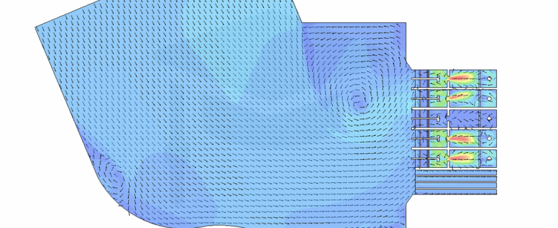
Canal pump bays and intake structures are the vital interfaces connecting open-channel water distribution networks to high-capacity mechanical pumping stations. Found extensively in flood control, agricultural irrigation, and municipal water supply systems, these structures must deliver uniform, low-turbulence flow to the pump impellers. Poor intake design leads to severe hydraulic anomalies that degrade pump efficiency and cause mechanical failure. Computational Fluid Dynamics (CFD) provides engineers with a high-fidelity visual and analytical toolkit to assess approach flows, eliminate costly physical modeling, and ensure optimal pump performance before construction begins.
Technical and Theoretical Description
From a hydraulic perspective, a canal pump bay operates on open-channel fluid mechanics heavily influenced by boundary layer transitions and free-surface dynamics. The flow field is governed by the three-dimensional Navier-Stokes equations, which must capture the deceleration and expansion of water as it transitions from a narrow canal into a wide pump bay basin. Because the approach flow is inherently turbulent and highly susceptible to flow separation along the bay walls, CFD simulations utilize advanced turbulence modeling. The Reynolds-Averaged Navier-Stokes (RANS) Shear Stress Transport (k-ω SST) model is universally applied due to its precision in resolving adverse pressure gradients and boundary layer separation.
A critical theoretical focus in pump bay design is the adherence to international standards, such as ANSI/HI 9.8 (Pump Intake Design). CFD models are used to evaluate specific hydraulic criteria: velocity uniformity at the pump throat, the angle of flow approach, and the elimination of free-surface and sub-surface vortices. Tracking the air-water interface is achieved via the Volume of Fluid (VOF) method. Vorticity is analyzed quantitatively using criteria like the Q-criterion or λ₂ method, which isolate and visualize coherent vortex cores. By mapping these rotational flow structures, engineers can mathematically predict whether a vortex will draw air down from the surface or generate localized low-pressure zones that cause mechanical vibrations.
Business Value of CFD Implementation
From a commercial standpoint, deploying CFD in canal pump bay engineering dramatically reduces capital expenditure (CapEx) and safeguards multi-million dollar mechanical assets. Historically, verifying an intake design required building a physical scale model, a process that takes months and costs tens of thousands of dollars. CFD replaces or minimizes this step, compressing engineering design cycles from months to weeks and allowing for rapid, cost-effective testing of multiple geometric configurations.
In terms of operational expenditures (OpEx), an optimized pump bay directly protects the pumping units from premature degradation. When a pump bay delivers non-uniform flow or harbors active vortices, the pump impellers experience asymmetric loading, leading to severe shaft vibration, bearing wear, and seal failures. This results in frequent unscheduled downtime and expensive overhaul costs. Furthermore, eliminating flow swirl and pre-rotation improves the overall hydraulic efficiency of the pumps, reducing energy consumption and lowering electricity costs over the lifetime of the pumping station.
Challenges of CFD in Pump Bay Modeling
Despite its analytical power, simulating a canal pump bay introduces distinct numerical and physical challenges. The primary obstacle is modeling the wide spectrum of geometric and flow scales. The domain must include a substantial portion of the upstream supply canal to capture realistic approach velocity profiles, yet it must also resolve the intricate geometries of pump bells, trash racks, and anti-vortex splitters where millimeter-scale mesh resolution is required.
Another significant hurdle is the transient nature of vortex formation. Free-surface vortices are highly dynamic, moving across the bay and changing intensity over time. Simulating these transient phenomena accurately requires time-dependent simulations with tiny time-steps, which vastly increases computational time and demands massive processing power. Furthermore, modeling the hydraulic impact of trash racks or debris screens adds complexity; simulating every single structural bar creates an unmanageable mesh count, forcing engineers to rely on porous media approximations that must be carefully calibrated to avoid distorting downstream velocity profiles.
Solutions for High-Fidelity Simulation
To overcome these scale and transient challenges, modern CFD workflows utilize advanced meshing strategies and specialized boundary conditions. Engineers address the scale discrepancy by utilizing multi-zone meshing combined with Adaptive Mesh Refinement (AMR). Coarser grids are used in the upstream canal, while the mesh automatically densifies around the pump bells and the free-surface zone to capture vortex filaments with high resolution. Trash racks are efficiently represented using anisotropic porous media models, where directional flow resistance coefficients are calculated based on empirical pressure-drop data.
To accurately capture the birth and behavior of transient vortices, steady-state simulations are used initially to establish the baseline flow, followed by transient RANS or Scale-Adaptive Simulations (SAS). Dynamic time-stepping is strictly controlled to maintain a low Courant number, ensuring numerical stability. Finally, to eliminate identified hydraulic flaws, engineers virtually test and iterate physical flow-correcting devices within the CFD model. These include adding localized floor splitters, back-wall cones, and submerged training walls. By validating the performance of these modifications in software, the final engineered blueprint guarantees a uniform, vortex-free flow that meets strict ANSI/HI compliance prior to concrete pouring.
Author: Caesar Wiratama
Find me on Linkedin