
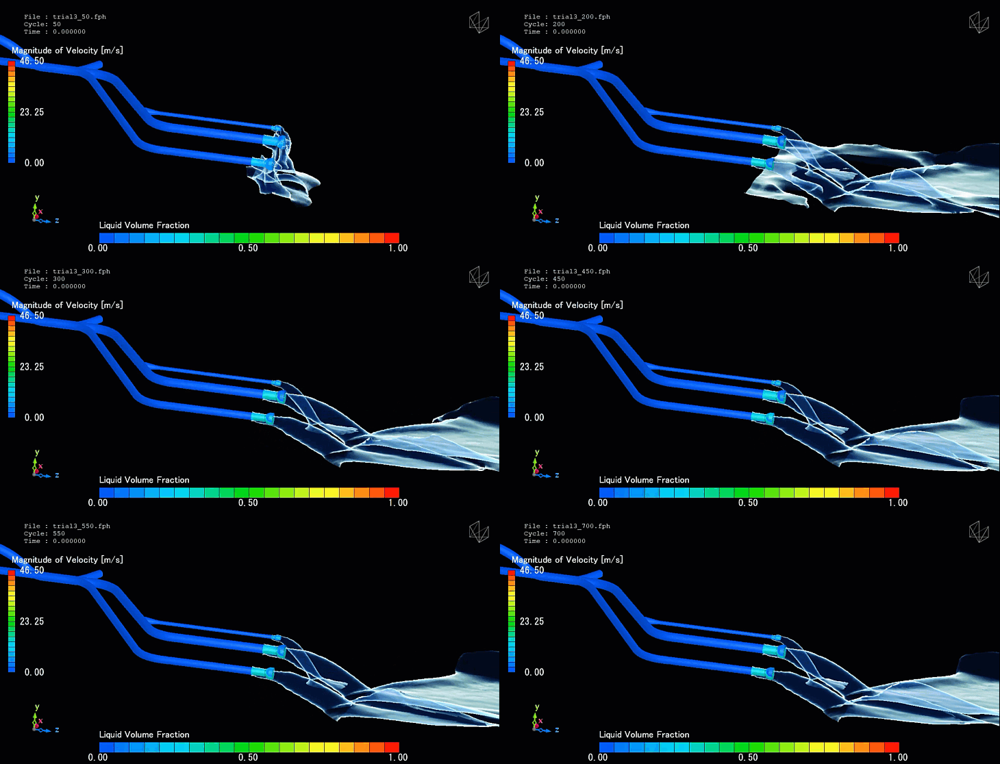
Dam piping systems, including penstocks, bottom outlets, and auxiliary conduits, are the critical circulatory networks responsible for water conveyance, power generation, and safe reservoir drawdown. These closed-conduit systems must withstand extreme internal pressures, high-velocity transient flows, and severe hydrodynamic forces. Because structural failures within deep-buried piping can lead to catastrophic internal erosion or un-controlled dam breaches, ensuring hydraulic efficiency and integrity is paramount. Computational Fluid Dynamics (CFD) provides engineers with a non-destructive digital laboratory to visualize complex internal flows, diagnose structural risks, and optimize system geometry with high precision.
Technical and Theoretical Description
From a fluid mechanics perspective, a dam piping system operates on complex, high-pressure internal hydraulics governed by the three-dimensional, compressible Navier-Stokes equations. Flows within these conduits are characterized by high Reynolds numbers, indicating intensely turbulent regimes. To accurately capture the energy losses and velocity distributions, CFD simulations utilize advanced turbulence closures, most notably the Reynolds-Averaged Navier-Stokes (RANS) Shear Stress Transport (k-ω SST) model, which excels at predicting flow separation near pipe bends, contractions, and valve boundaries.
A primary theoretical focus in closed-conduit dam hydraulics is the modeling of transient phenomena, specifically hydraulic transients or “water hammer.” When control valves close rapidly, kinetic energy converts into pressure waves that propagate through the fluid column, described mathematically by Joukowsky’s equation. CFD models this by treating the fluid as compressible and accounting for pipe wall elasticity via coupled boundary conditions. Furthermore, in high-velocity drop-shafts or low-level outlets, multi-phase flow physics must be accounted for using the Volume of Fluid (VOF) method to capture the free-surface transition and air-water interactions, ensuring that negative pressures do not develop and trigger cavitation.
Business Value of CFD Implementation
From a commercial standpoint, implementing CFD in dam piping design and forensic engineering offers significant capital expenditure (CapEx) savings and asset risk reduction. During the design or modernization phase, CFD enables rapid virtual prototyping of manifold junctions, bifurcations, and valve housings. This optimization lowers local hydraulic head losses, directly translating to higher power generation efficiency in hydropower penstocks and maximizing revenue over the dam’s operational lifecycle.
In terms of operational expenditures (OpEx), CFD prevents catastrophic, multi-million dollar structural failures. It allows asset owners to identify localized high-velocity zones prone to severe wall thinning before physical wear occurs. For aging infrastructure, CFD acts as a powerful diagnostic tool; engineers can simulate “what-if” emergency closure scenarios safely in software. This eliminates the risk of performing dangerous, full-scale physical water hammer tests on compromised, decades-old piping systems, thereby ensuring operational continuity and regulatory compliance without risking the asset.
Challenges of CFD in Dam Piping Modeling
Despite its analytic power, simulating dam piping networks introduces steep computational and physical challenges. The foremost obstacle is capturing the vastly different scales of the system; a penstock may run for hundreds of meters, yet the boundary layer fluid physics, valve seal gaps, and cavitation micro-bubbles require millimeter- or micron-scale resolution. Resolving these localized features demands high mesh densities and immense computational resources.
Another major hurdle is accurately capturing transient multiphase physics, particularly air-pocket entrapment and rapid column separation during vacuum events. When a valve closes or opens quickly, water can vaporize locally if pressure drops below the vapor pressure threshold, creating a vapor cavity. The subsequent collapse of this cavity generates micro-jets with extreme localized pressures. Simulating this transient cavitation phase-change with high fidelity requires highly sensitive, compressible multi-phase tracking algorithms that are prone to numerical instability if the time steps are not precisely managed.
Solutions for High-Fidelity Simulation
To overcome these multi-scale and transient challenges, modern CFD workflows deploy specialized numerical techniques and coupled physics solvers. Engineers resolve the geometric scale discrepancies by using multi-zone meshing paired with prism layer inflation along the pipe walls to capture the steep velocity gradients of the turbulent boundary layer. Advanced control valve movements are simulated using dynamic meshing or overset (chimera) grid techniques, which allow solid boundary geometries to slide or rotate through the fluid domain without destroying mesh quality.
To stabilize and solve complex water hammer and cavitation issues, compressible fluid definitions are paired with specialized cavitation sub-models, such as the Rayleigh-Plesset equation, which dynamically tracks the growth and collapse of vapor bubbles. To assess the true structural impact of these hydraulic forces, fluid pressure fields are mapped directly onto structural grids via Fluid-Structure Interaction (FSI) workflows. This coupling allows the fluid pressures to inform Finite Element Analysis (FEA), ensuring that pipe wall thicknesses, reinforcement rings, and anchor blocks are perfectly engineered to withstand maximum transient surge pressures.
Author: Caesar Wiratama
Find me on Linkedin